The
function of the equipment terminals is so broad and complex that it is
hard to explain easily (or concisely). In general it contained equipment that
was chiefly provided for direct support of the missiles and their many
support systems. From climate control and utility air supply to
targeting, fuzing and course calculation, the equipment terminals
encompassed many critical systems and functions. Suffice to say,
they were (at the time) filled with some of the most advanced
technology developed for military use, second only to ongoing projects
yet to be deployed.
The
Equipment Terminals contained aerospace operating equipment (AOE1),
aerospace ground equipment (AGE2), power distribution, switchgear,
hydraulic pumps, lines and a myriad of other gear to
support the targeting, checkout, exercise and launch of the Titan I
ballistic missile. Each of the four levels contained equipment
geared toward different specific tasks and services needed for support
of the Titan I missiles.
1
Equipment that makes the missile able
to complete its mission. e.g. to launch, find its target, etc.
2
Equipment that supports AOE.
e.g. testing, repairing and calibrating AOE.
While
placement and type of equipment used tended to vary from site to site,
the following describes the systems and facilities installed in the
equipment terminal levels according to the Titan I dash-1 technical
order publication (T.O.
21M-HGM25A-1-1) which provides a general overview of
the operational complex. The highlighted
text sections below are taken directly from the dash-1 Section I.
LEVEL
I - Power Pack Room
Level
I of the equipment terminal (figure 1-13) is divided into a power pack
room and an electrical room. The power pack room contains the
cycling control station and power pack equipment which supplies
hydraulic pressure for operating the launcher system. The
electrical room contains the motor control center and the logic racks
for the launcher hydraulic equipment.
This
was the deepest, darkest and filthiest area of the equipment
terminals-- the lowest floor, it was the basin for all the water, dirt
and accumulated junk discarded by the salvage crews from the upper
levels. At 724-C, one of the three equipment terminals were
completely flooded at this level. Only equipment terminal #1 was
consistently above water and completely dry during my visits.
Equipment terminal #2 showed signs of having been flooded in the past:
underneath the floor there was a disgusting slough of thick, dark red
water that looked like congealed blood. A nasty crust had formed
on the surface of this sludgy mire and it was speckled here and there
with festive colonies of bright white mold visible through large (and
hazardous) gaps opening into the sub-floor space below.
My
personal estimate would place the dark coagulation at the very bottom
in the range of 2 to 3 feet deep-- enough to ruin your tap shoes and
trousers and make walking back to the surface a real displeasure
unless you had donned waders upon entering.
|
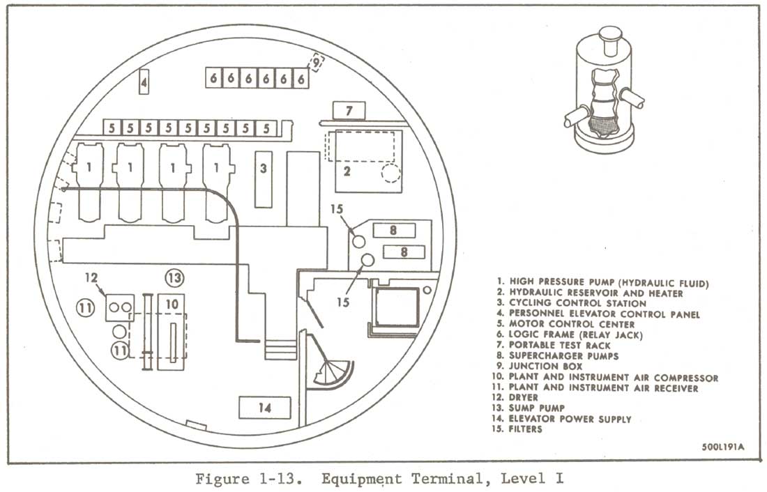
Equipment
Terminal Level I - General operational complex layout as illustrated in
the dash-1 tech order
|
The
water had largely devastated level one at E.T.#2, leaving a crust of
black mold and water lines marked by heavy corrosion. Hoses and
flexible electrical conduit covered the floor amongst the piles of
discarded and sodden fiberglass pipe insulation and jumbles of
metallic junk.
|
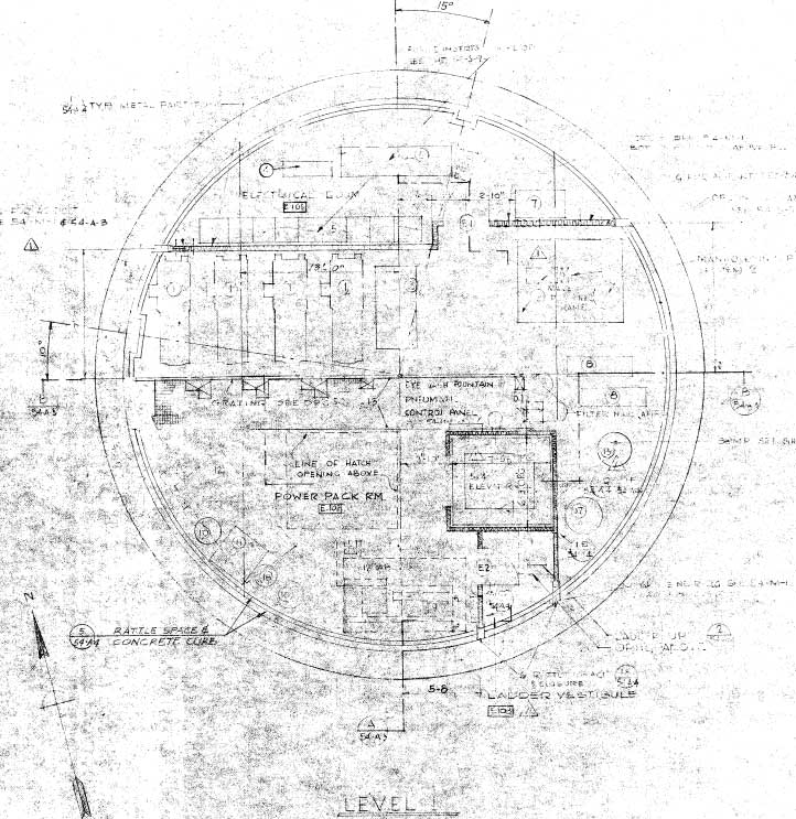
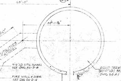
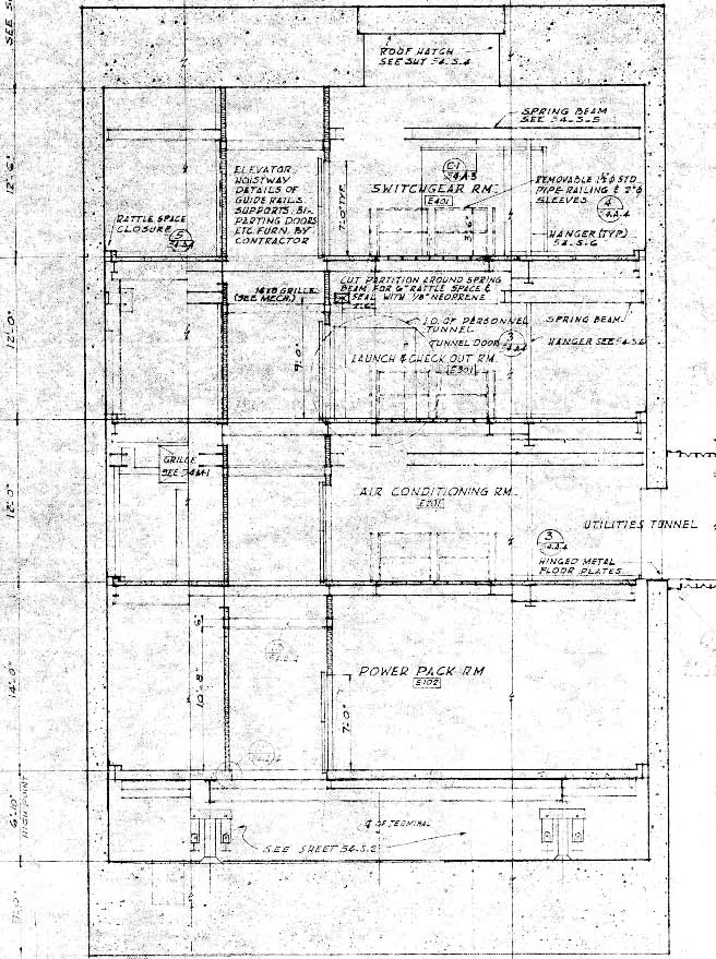
Provided
for comparison, the Lowry AFB floor plan for Level I of the equipment
terminal. This illustrates some of the differences exhibited
between the general descriptions given in the tech order publication and
other illustrations and the actual operational sites. Though not a
very clear image, it is clear that the locations of the elevator shaft
and the presence of a spiral staircase are a few obvious disagreements
between the AF documents and the as-built drawings. Relative size
and locations of equipment given outside of the blueprints are at best
guidelines for the operational complexes which tended to differ greatly.
|
Hydraulic
pumps had once dominated the area and piping had been routed under the
floor and covered with steel grille-type flooring. Much of this
flooring had been removed or otherwise disturbed leaving ample
opportunity to take an inadvertent dive into the scum below.
Just
about all the equipment at E.T.#1 had been removed save for the
cycling control station for the hydraulic systems and the very large
fluid reservoir (a ladder was needed to reach the top). The
metal partition of the largely empty electrical room was still in
place and a large shock mounted platform for the air instrument air
compressor was still present. At E.T.#2 one last interesting
relic that remained was the sewage ejector-- a squat, green, steel
pressure vessel of the utmost importance to my way of thinking.
I was surprised to see only one and no back up unit. This
invaluable device would force all waste water to the surface from
about 80 feet below ground and into the sewage spray pond.
|
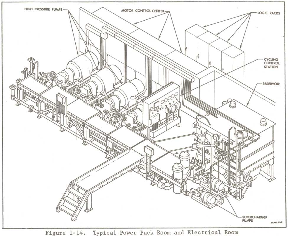
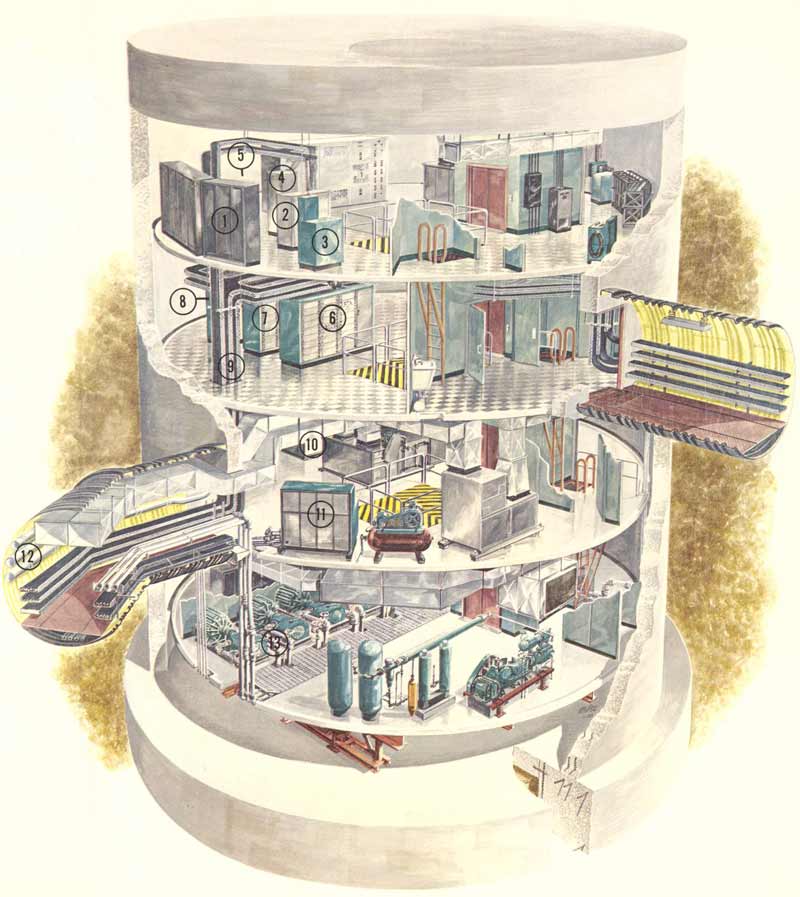
A
very good illustration of the hydraulic pumps and accumulator (reservoir
lower right) and associated equipment on Level I. Essentially,
only the hydraulic accumulator and cycling control station remaining at
724-C today. The pumps, platforms, motor control and logic racks are all
gone at 724-C. Other sites have some of the logic racks remaining,
but they are empty, the components are long gone.
|
LEVEL
II - Air Conditioner Room
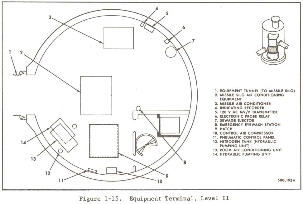
Level
II of the equipment terminal (figure 1-15) contains the missile air
conditioner and the missile silo air conditioning equipment. The
missile air conditioner supplies heated or cooled air to maintain the
proper temperature in the Stage II transition compartment,
between-tanks compartment, and Stage II engine compartment. The
missile silo air conditioning equipment supplies conditioned air to
the missile silo. Level II also contains a hydraulic pumping
unit that supplies hydraulic fluid to fill, bleed, and pressurize the
hydraulic equipment in both missile stages.
Level
II was crowded with dismantled ductwork, stacked about the floor
between large heating and AC units. The missile air conditioning
ductwork had been left in place and ran into the utilities tunnel
which was carpeted with rusty muck and mineral salts. Heavy
hydraulic lines with massive square connections emerged from the floor
to join the ductwork on its way to the silo.
|
Equipment
Terminal Level II - General operational complex layout as illustrated in
the dash-1 tech order
|
To
me, the most puzzling thing about level II was that the ductwork
had been taken down and then left behind. Why did they
bother?
This
level was dry at E.T.#1 except for some drippage from the surface
access hatch above on level IV. The hatch cover had been removed
during salvage of course, and then quickly replaced without concern
for the integrity of the environmental seal. This was the source
of most of the water in equipment terminal #1.
|
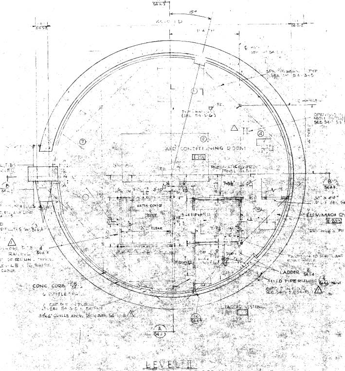
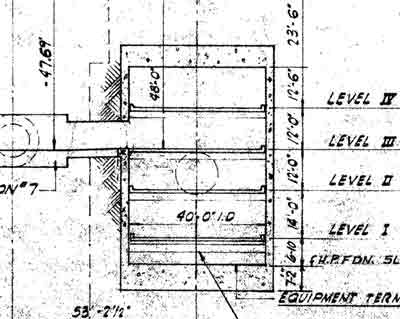
Provided
for comparison, the Lowry AFB plan for level II of the equipment
terminal. Though this drawing offers very little detail aside
from the location of the floor access hatch and elevator shaft.
Most of the missing detail is heating and air conditioning units and
lots and lots of ductwork leading out of the level via the utilities
tunnel or to other levels.
|
LEVEL
III - Launch and Checkout Room
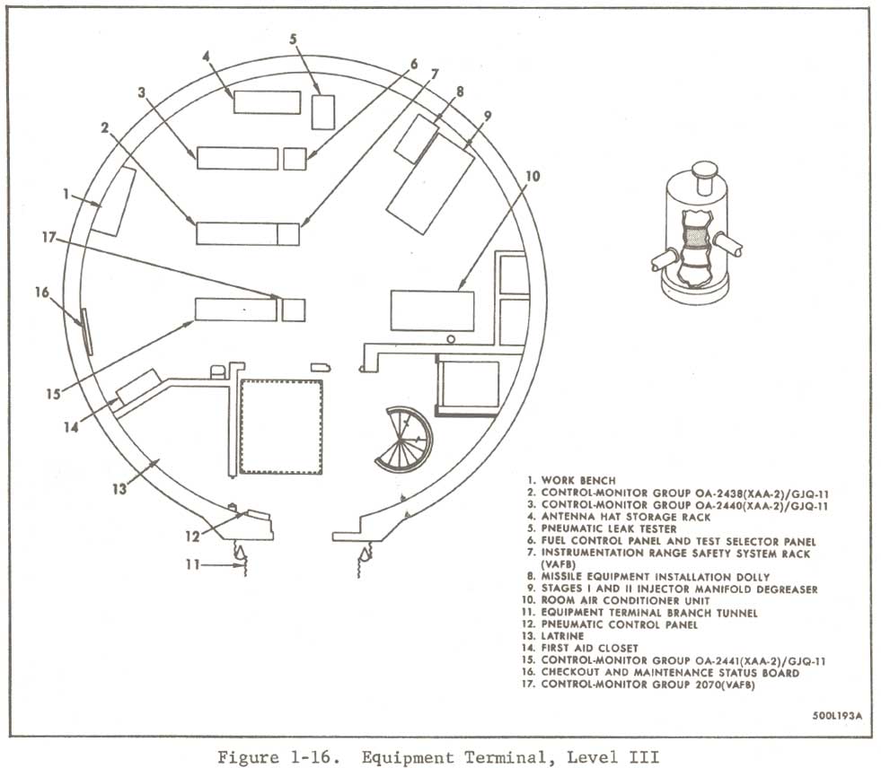
Level
III of the equipment terminal (figure 1-16) contains launch and
checkout equipment necessary to launch a missile or perform checkout
of the following subsystems: engine control, flight control, launch
sequencer, re-entry vehicle, electrical, missile guidance, and
propellant loading and pressurization systems.
During
operation, this level had mostly contained large racks filled with
logic equipment. All of them have been removed, and though I did
see racks at 725-A back in 1994, they were all empty. No racks
were present at all in the equipment terminals at 724-C by the time I
arrived in 2000.
|
Equipment
Terminal Level III - General operational complex layout as illustrated
in the dash-1 tech order
|
There
really wasn't much left to see at all on level III. There
was miscellaneous junk and conduit strewn about and little
else. This level does however have a latrine with one sink,
one stall and one urinal. An antique Boraxo dispenser
(empty, I checked) hung near the sink. Not much to see there
besides some truly filthy porcelain fixtures reminiscent of the
worst public restrooms you've ever been faced with on a long road
trip during the 1970's-- in the South.
|
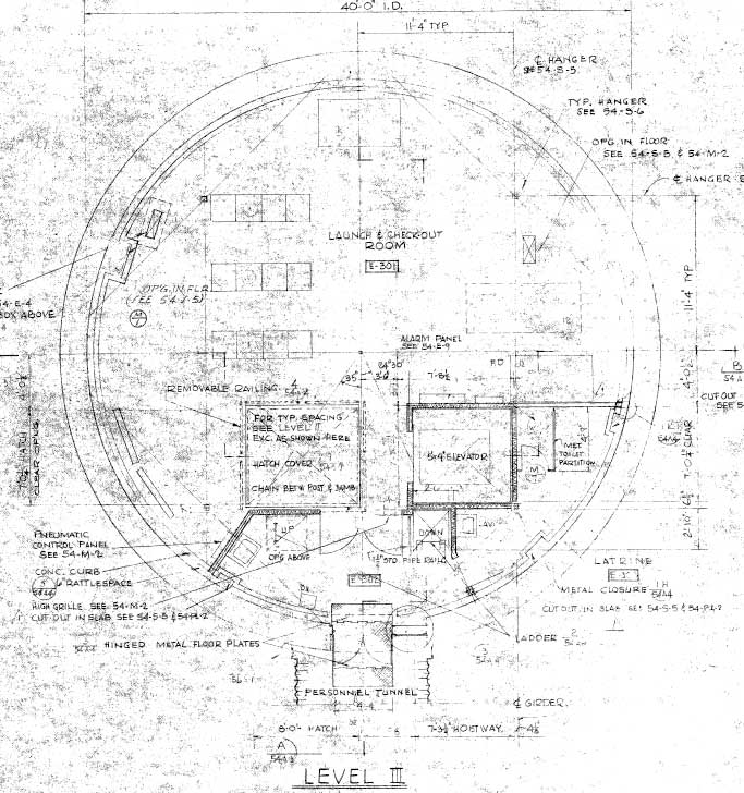
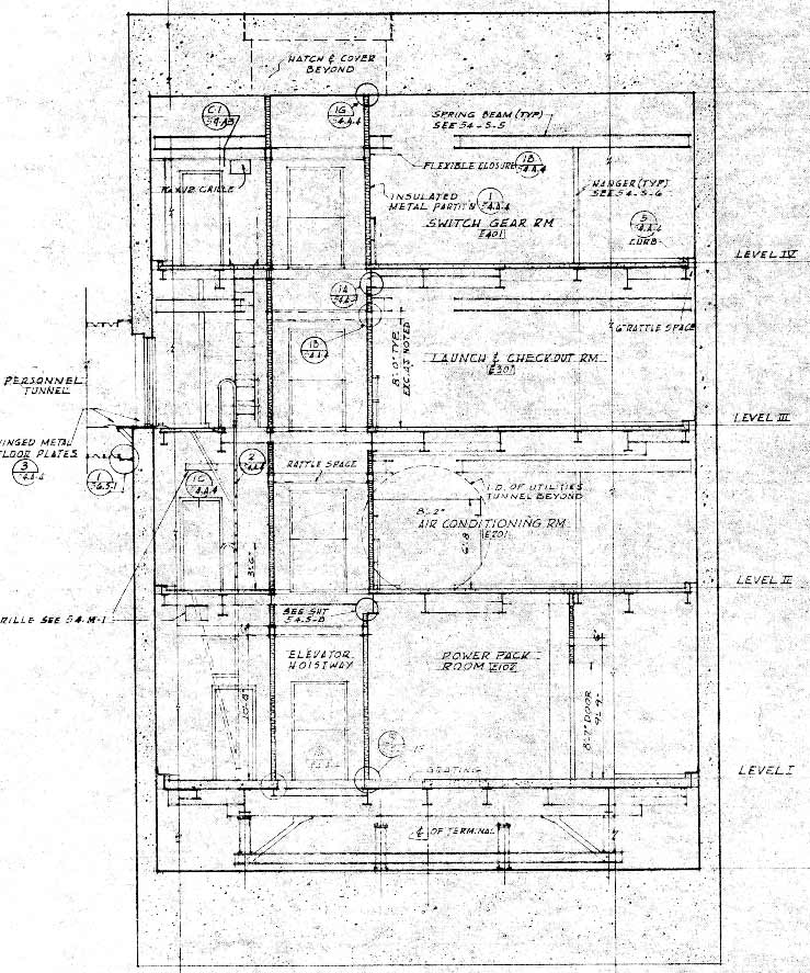
Provided
for comparison, the Lowry AFB plan for level III of the equipment
terminal. This drawing more clearly shows the location of the
hangers that supported the structure of levels II-IV. If you look
at the upper right quadrant you can see a reference "TYP. HANGER,
SEE 54-S-6" with an arrow showing its location as a small
square. This denotes the vertical support and one is visible in
each quadrant. The thin lines that intersect each of the squares
represents a heavy steel I-beam from which the vertical support is
suspended.
|
LEVEL
IV - Switchgear Room
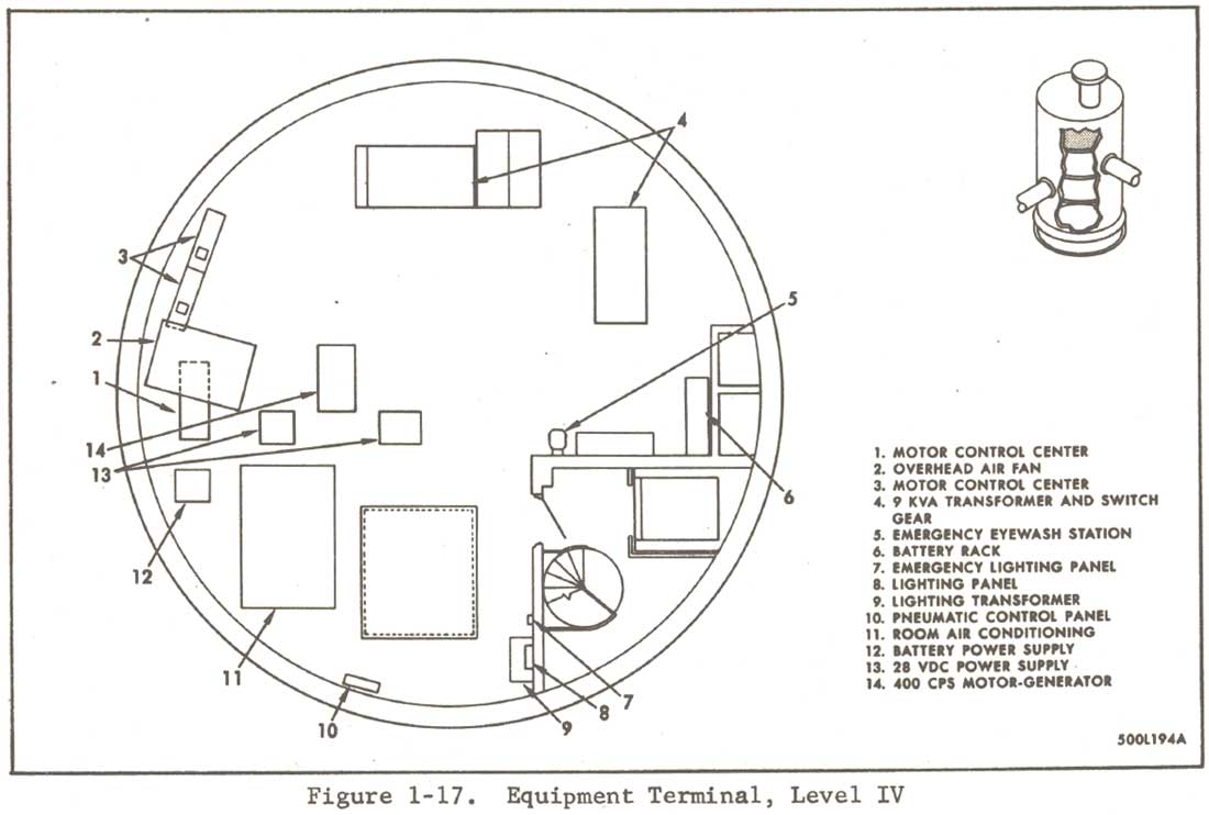
Level
IV of the equipment terminal (figure 1-17) contains the equipment that
supplies and distributes electrical power to the launcher area.
This level contains motor control centers, a power switchboard, a 400
CPS motor-generator, two 28 VDC power supplies, a battery power
supply, a 9 KVA transformer, and transformer substations.
Like
level III, level IV was pretty barren as well. There was a large
room air conditioner unit and a couple heavy duty battery racks (sans
batteries of course) but aside from that there was the just the
omnipresent dirt brought in by infiltrating water, and the usual junk,
insulation and an odd hose or two laying about.
|
Equipment
Terminal Level IV - General operational complex layout as illustrated in
the dash-1 tech order
|
Looking
up at the ceiling, the poorly-replaced hatch cover loomed overhead,
ringed with obvious seepage and rust. I suppose it makes sense
that the level closest to the surface had the least left in it since
it was the easiest to access.
Some
cable trays emerged through the floor and an empty elevator shaft
beckoned the clumsy or unwary (the doors were all forced open and
the car was on a lower level) through its gaping doorway.
|
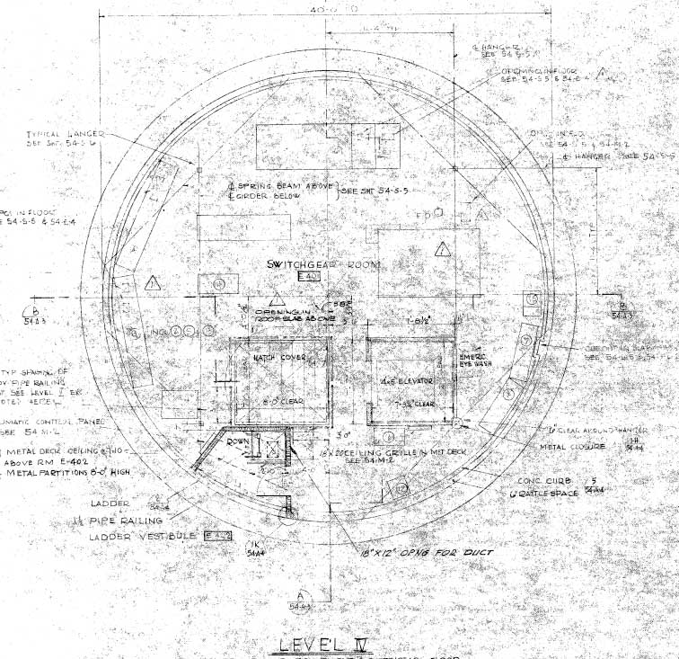
Provided
for comparison, the Lowry AFB plan for level IV of the equipment
terminal. Note once again the location of the elevator and the
absence of a spiral staircase shown in the previous diagram.
|
In
the next section, we'll take a look at the construction of the
equipment terminals and finally get a look at some photos of the inside.
Click
the link below to see more about the equipment terminals or select
another location from the map below.
Equipment
Terminals Part II
Current
Location: Equipment Terminals
|
Where
would you like to go next?
|

|
Contact
| Site Map | Links |
Hosted by
InfoBunker