Power
House Air Exhaust
This
area is pretty self-explanatory for the most part and as expected was
largely built around the discharge of diesel exhaust from the
generators. There were other effluvia discharged here such as
waste heat, steam, and corrosive, volatile and toxic fumes associated
with various processes and the operation of the machinery in the Power
House. In short, this structure served as a giant tailpipe.
|
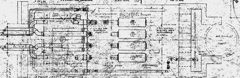
A
terrible-quality* top view diagram of the end of the exhaust tunnel showing the
four huge mufflers and the exhaust stack.
|
Though
in later revisions, the air intake and exhaust structures at other sites
would be radically redesigned, becoming much smaller and more cost
effective to construct and maintain, they were still impressive in
size. As they evolved from the much larger horizontally-oriented
configuration you see here, to the vertically-oriented and more compact
arrangement, they would be more effectively measured in feet than yards.
*
My apologies
about the blueprints in this section. The images were scanned from
nth-generation blueprint reproductions from copies made using the
standard diazotype method for copying blueprints. Later
generations using this method can tend to become very "muddy"
and end up looking dirty, smudged and damn hard to make out. I did
what I could to clean them up, but I am sad to say, this is the best I
could do.
|
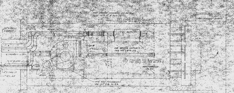
A
terrible-quality side view of the end of the exhaust tunnel showing the
fan, blast valves and upper level where the mufflers are located.
|
Not
including the connecting access tunnels, the air intake and exhaust
structures were large enough to accommodate a semi tractor/trailer,
whereas the later structures were roughly 40 feet in diameter. No
matter which, the function was fairly simple, and that was to channel
all undesired exhausts, whether from combustion or otherwise, to a
central location and eject them to the surface where they would be borne
away from the complex by the winds.
|
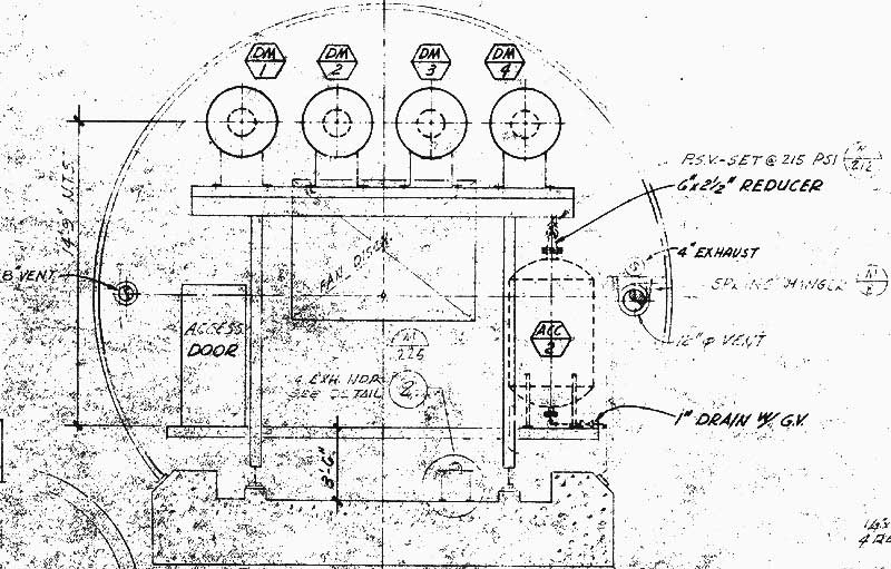
Cross-section
of exhaust tunnel at the mufflers
|
An
access tunnel (shown below) branched off of the mezzanine level leads
past the imposing diesel storage tanks to the exhaust fan. At that
point, the barrier between "inside" and "outside" diminishes
to one steel bulkhead while the complex is in a "soft"
state. Soft meaning that the blast valves are open and the site is
technically vulnerable to overpressures from atomic blasts as it takes
in air and expels exhaust.
|
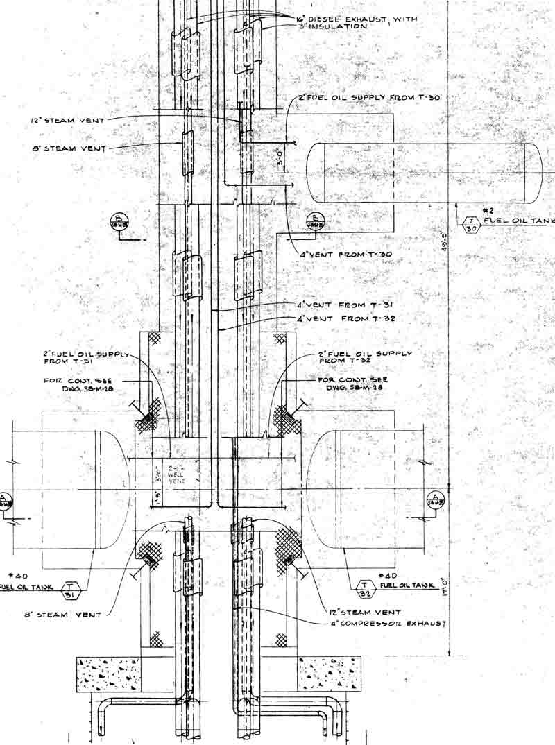
Above
view of exhaust tunnel section adjoining the Power House mezzanine
level. Here you can see the location of the 5000-gallon diesel day
tank, and the two 67,000-gallon main diesel storage tanks. Just
past the bottom of this diagram, the tunnel widened where the 175,000
cfm fan was situated.
|
The
blast valves waited for any sign of a nearby blast that would trigger
them to slam shut in a fraction of a second, protecting the interior
from the shockwave. After the destructive forces had passed over,
the blast valves would re-open allowing the complex to breathe and
operate. The grim reality of fallout was that once the blast
valves opened again, contaminated air would be drawn into the complex.
|
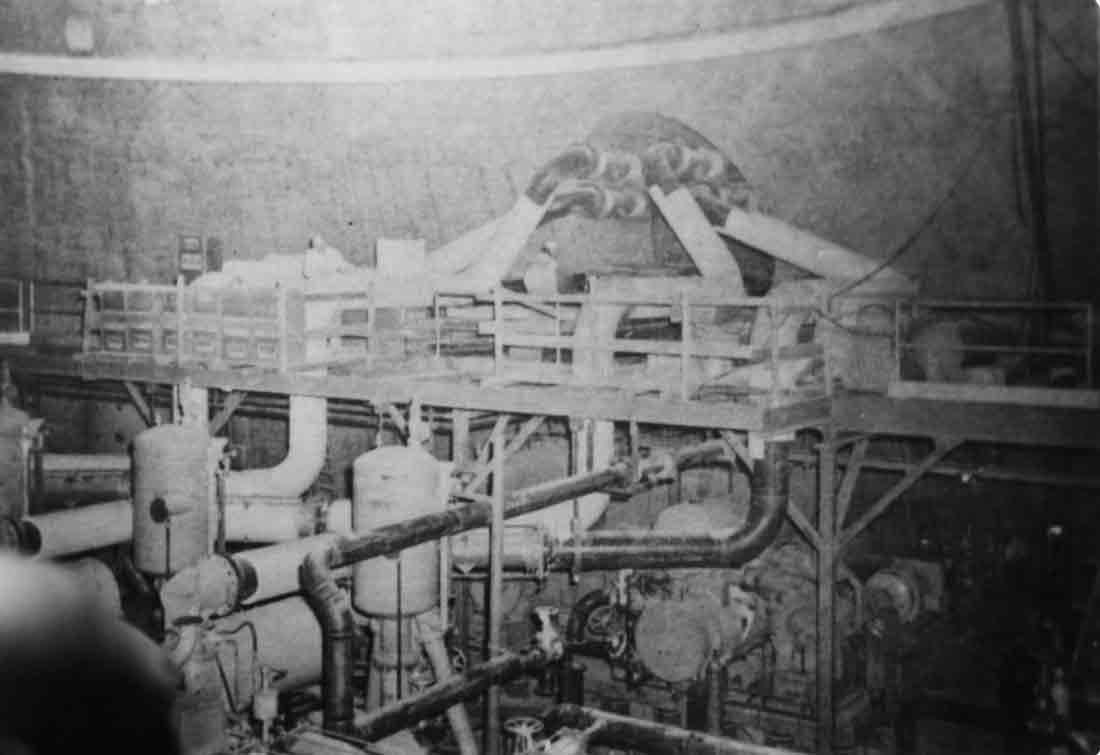
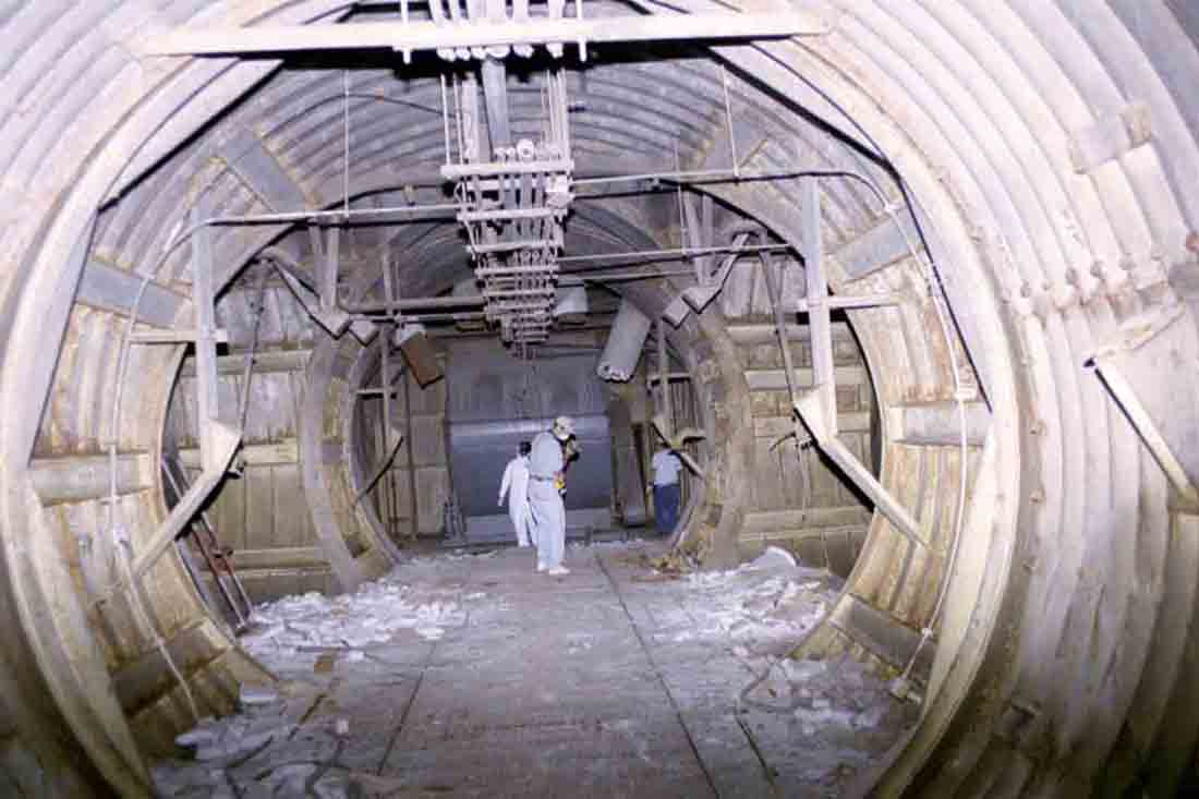
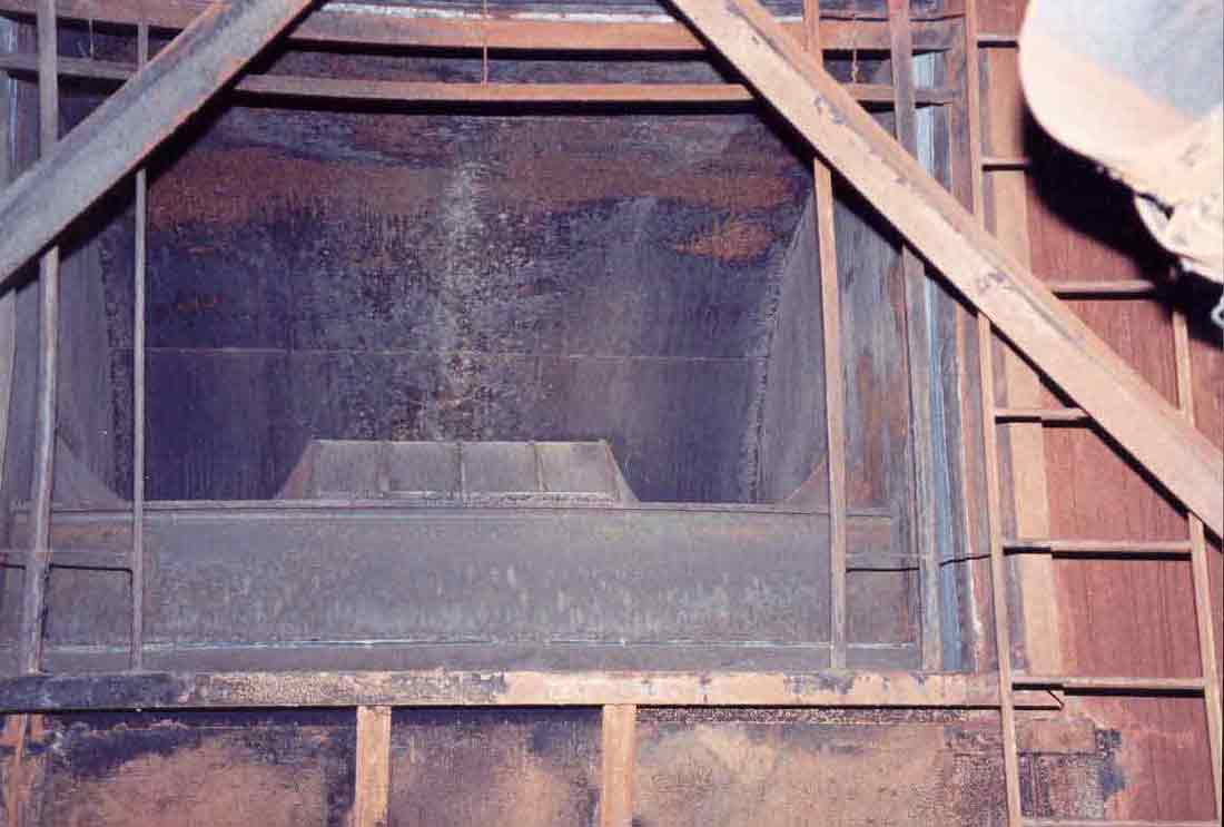
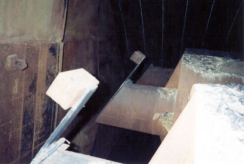
This
construction photo is the best source I have for a near-operational
image of the entrance to the exhaust tunnel. You can see here that
the 3" insulating layer of asbestos plaster is still in the process
of installation on the four huge 18" dia. exhaust conduits from the
generators. I have yet to come across operational photos of the
exhaust tunnel unfortunately.
|
|
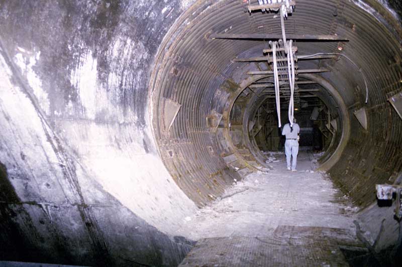
Here
is the present-day appearance of the same entrance shown in the previous
photo. The steel exhaust conduits have been recklessly stripped of
their insulation and cut free from their supports with torches and
removed. The asbestos plaster was left to lay where it fell and
ground into powder underfoot leaving eerie white residue, sometimes
several inches thick, covering the floor.
|
Some Words on
Asbestos Undisturbed
asbestos insulation under a good layer of paint or sealer is virtually
harmless if left alone. The trouble comes from damage to the paint
or the insulation itself that allows dust particles containing asbestos
to become airborne. Crushing this plaster into fine powder even in
small amounts is enough to close a public building for weeks while
cleanup is conducted.
Because of the onerous costs of abating asbestos from public buildings, most
buildings where asbestos was widely installed have instead had the
asbestos "stabilized" in one way or another. This
constitutes sealing over insulation or material that contains asbestos
so that it cannot easily be disturbed and thereby become friable (easily
crumbled) and prone to become airborne where it can be inhaled.
Obviously this was never done in the 1960's so this area of the complex
represents a "worst case scenario" of asbestos in its most
disturbed state and in exposure to unprotected visitors.
While
it is widely held that the dangers posed by asbestos are largely
overstated (please note, this is not my personal position on the matter,
and I will not substantiate on this further. Take that as you
will.), it would be wise to err on the side of caution and avoid unnecessary
contact with a material known to cause cancer and several forms of
serious respiratory disorders that can shorten one's life
considerably. Personally, I would hesitate to say that the dangers
posed by asbestos are wildly overblown, but let's be frank, nothing
makes a lawyer smile like a class-action lawsuit, if you get my drift.
For
more general information on asbestos, check Wikipedia's entry here.
|
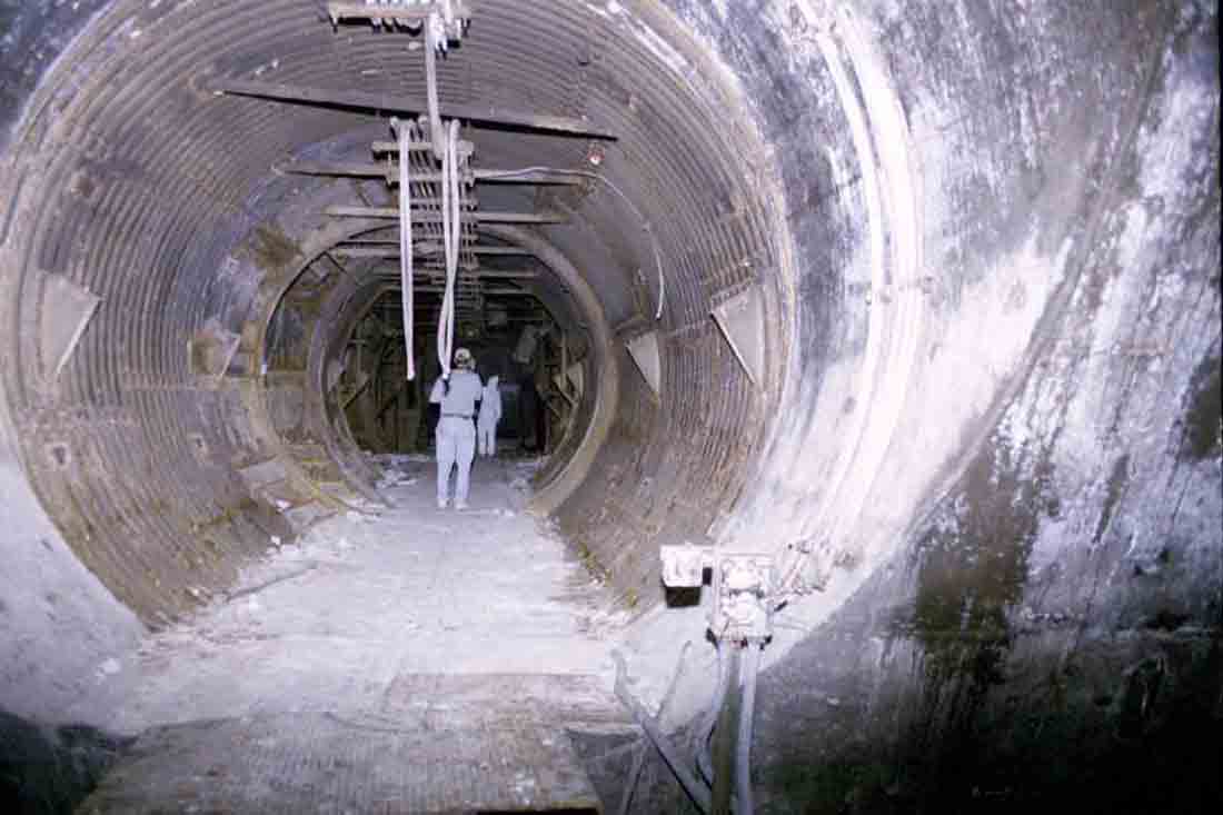
This
is the area of the complex that poses the most danger by
contaminants. The ratio of asbestos in plaster used for this
application would be the highest-- likely 20% or higher, and its
condition is about as bad as it can get. That ain't all-purpose
flour you see on the floor.
|
As
far as the function of this area, there is not much else to tell.
On inspection, I found it difficult not to worry about all the harmful
dust in this area, which nearly overshadowed the constant general danger
associated with being in such an environment. In time, I must
admit that I became more relaxed and perhaps a bit complacent about
roaming around inside the complex. This is a dangerous state of
affairs and is wisely discouraged.
Over
the two years I stood watch over 724-C, I had a few unusual requests
amid showings to potential buyers (no, I was not the owner, just
a caretaker of sorts). One person wanted to film a
post-apocalyptic sci-fi film in the complex, and another wanted to film
a small independent documentary. I am sad to say that these
requests were declined due to the ungodly liability involved in such
enterprises.
However,
to make my point about complacency in regards to safety, there was a
film crew down in the site after it was purchased. I was told that
MTV did a shoot about urban exploring and featured 1C in their
program. I don't know if this show ever aired, or was in fact just
a myth. (can anyone verify this?) At some point a producer
or director (I cannot recall which) is said to have become lapse in his
attention and stepped right off a gap in the flooring of one of the
tunnel junctions near the escape hatch and dunked himself completely in
the filthy water. I didn't hear of any injuries, but I can tell
you that I cringe to think of being submerged in that muck containing
the liquefied corpses of numerous small animals and lots of other
filth. Yuck!
|
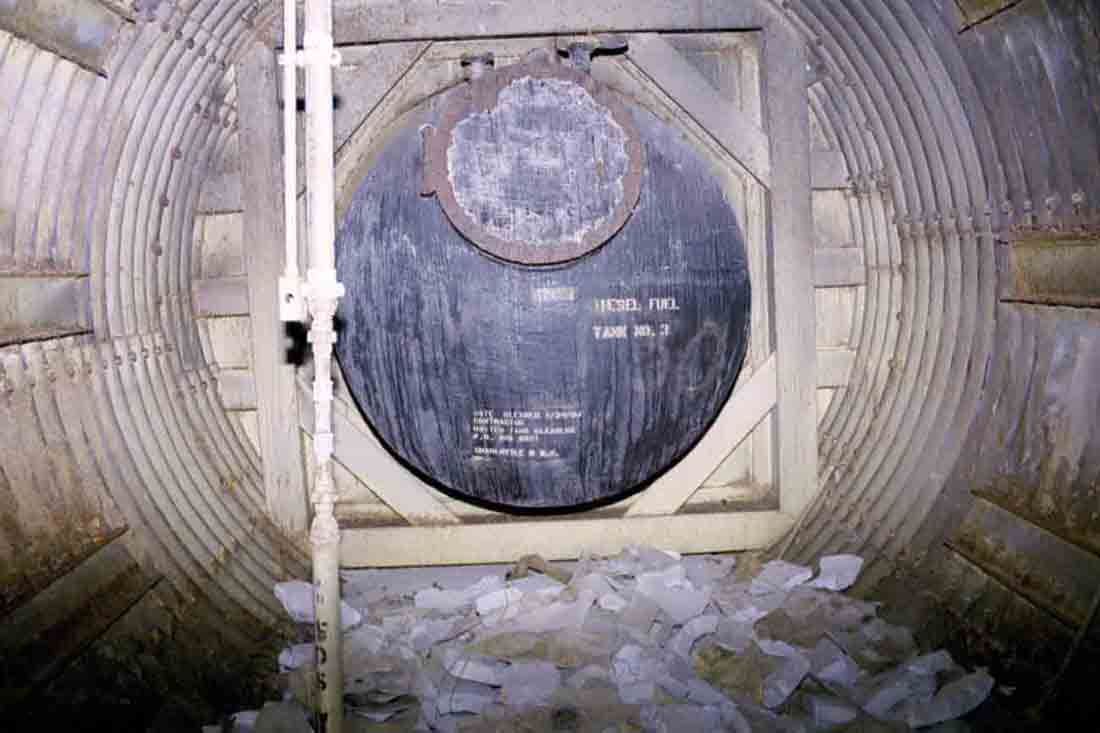
Diesel
tank No. 3, or the 5000 gallon day tank, housed in an alcove off of the
exhaust tunnel. This tank has an outside diameter of 6' and is 24'
long. A day tank is typically a tank intended to house an average
day's usage of fuel. This tank was supplied by two much larger
tanks located further along the exhaust tunnel.
Resting
on the floor is enough asbestos to elicit screams of raw horror from any
facilities manager of a public or private building. Well in the
U.S. anyway... Lots of countries would simply pick it up and throw
it in the trash as its use is not banned in many places.
|
|
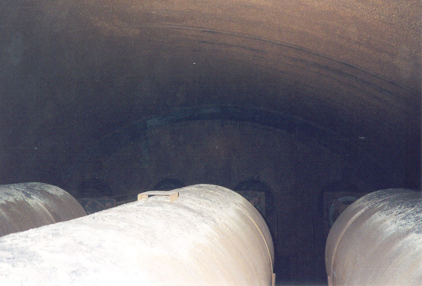
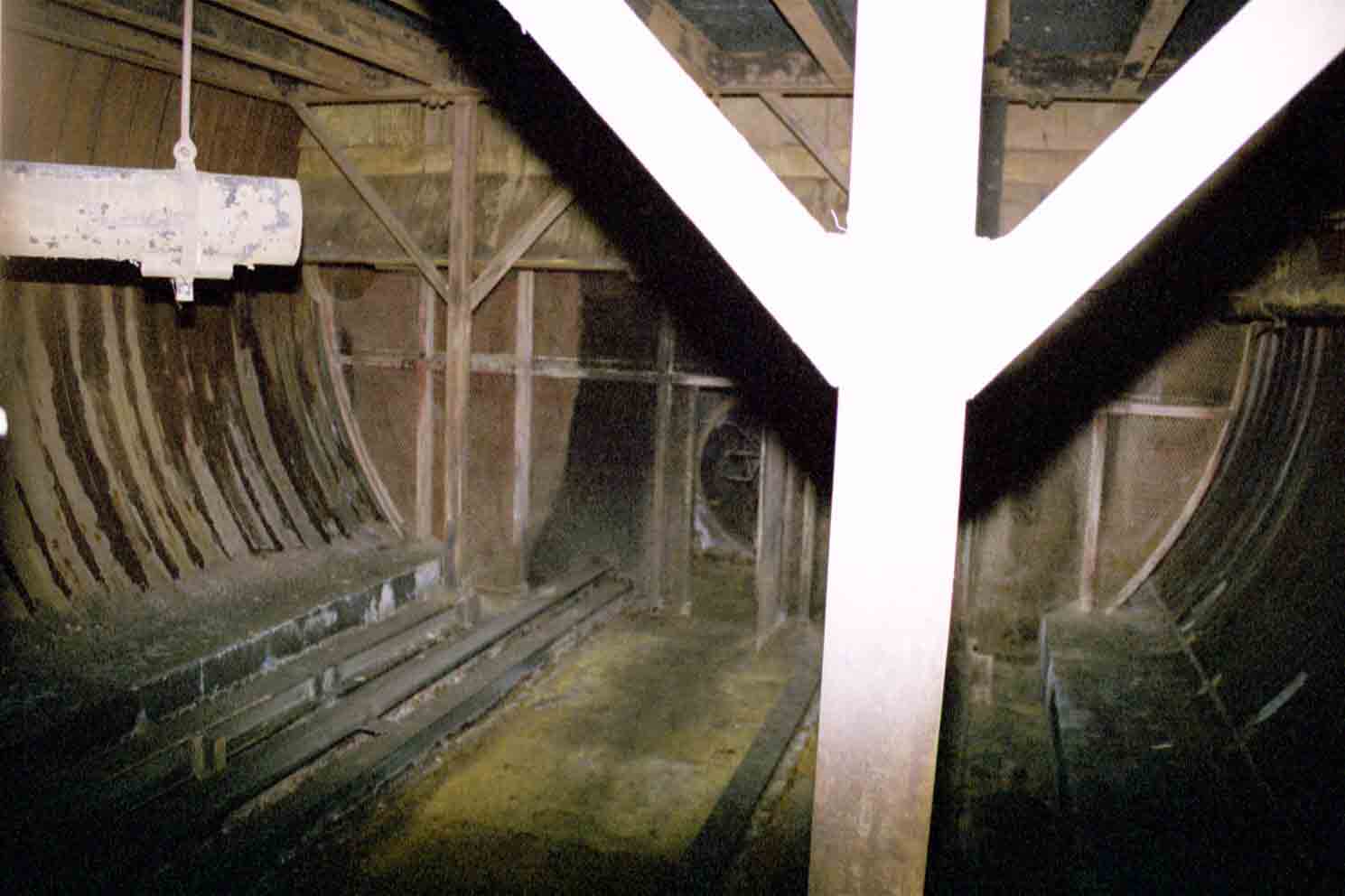
Further
along the tunnel there is a junction where the two 67,000-gallon diesel
tanks are located-- one on the right and another on the left. Dead
ahead you can see the gray enclosure for the fan and the stubs of the
exhaust conduits stabbing downward from the darkness above.
|
If the 5000-gallon day tank was
in fact an accurate measure of average daily fuel consumption, then with
full tanks the Titan complex could expect about 27.8 days worth of
run-time before requiring a refueling. I am fairly certain however, that
refueling was done more frequently than once a month.
As
you can see, there is a sub-floor here with the usual steel
decking. This floor continues up to the bulkhead near the fan.
|
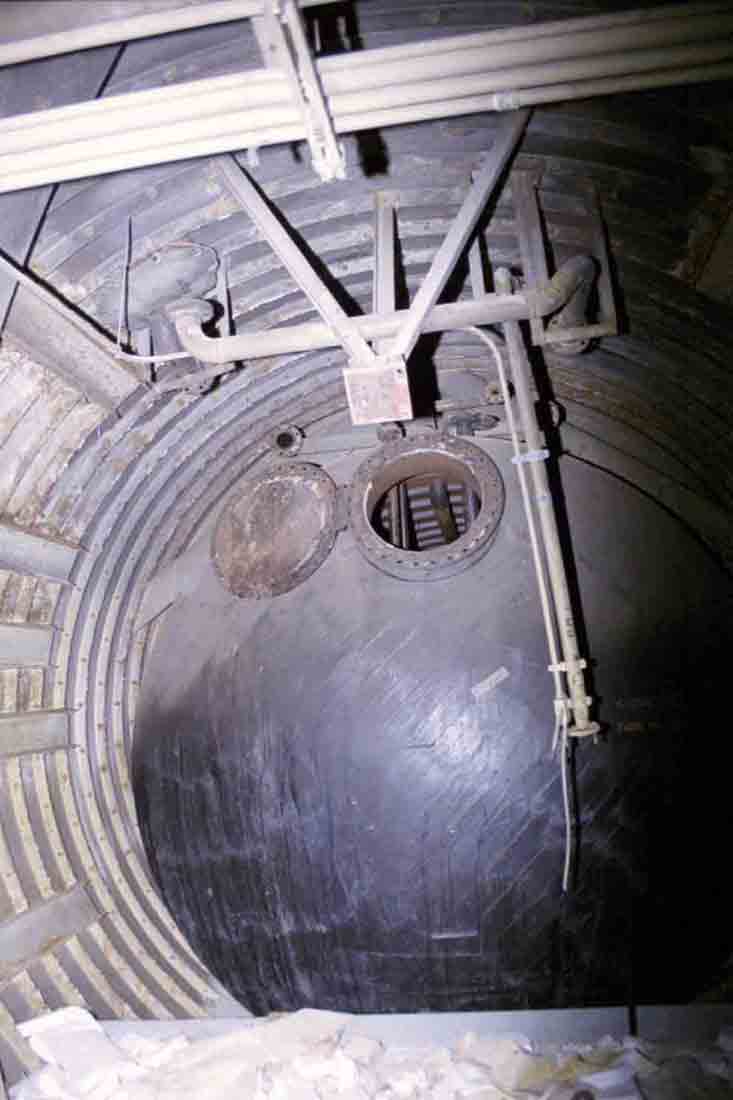
Diesel
tank No.2 has a capacity of 67,000 gallons, has an outer diameter of 12'
and is 80' in length. The access hatch is about 18"
across. Ask yourself how well you could fit through there!
|
I am
not sure why the access hatches are open on the tanks. Perhaps the
fuel was siphoned out directly or a visual inspection was required to
verify the removal of the diesel.
|
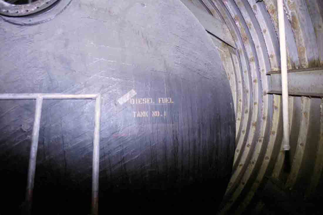
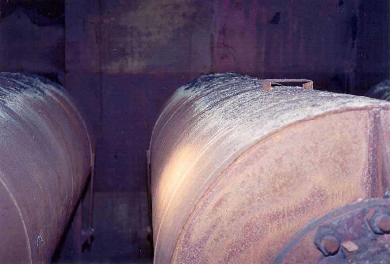
Diesel
tank No.1, same as No.2-- 12'x80' and 67,000 gallons. Note the
section of steel railing propped against the tank. This
facilitated a peek inside which revealed standing liquid in the bottom
of the tank. Not sure if it was collected condensation or diesel
residue. Unlike tank No.3, tanks 1 and 2 said nothing about having
been cleaned, remediated or otherwise conditioned since the site's
closure*.
Oftentimes
these single-walled fuel tanks were first cleaned and then filled with
sand or concrete by (or on behalf of) the EPA to prevent their
re-use. Double-walled containers are the modern standard for
environmentally sound fuel storage, and single-walled tanks are no
longer legal for underground fuel storage. 725A and I believe 724A
have had the tanks "stabilized" in one of the above fashions.
*
As of 2003. I
am fairly certain this has not changed, but cannot verify this.
|
|
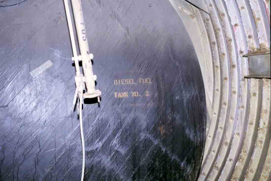
Another
view of tank No.2. One of the fuel supply lines to the day tank,
protrudes in the foreground. Fill connectors were located at the
surface near the entry portal.
|
|
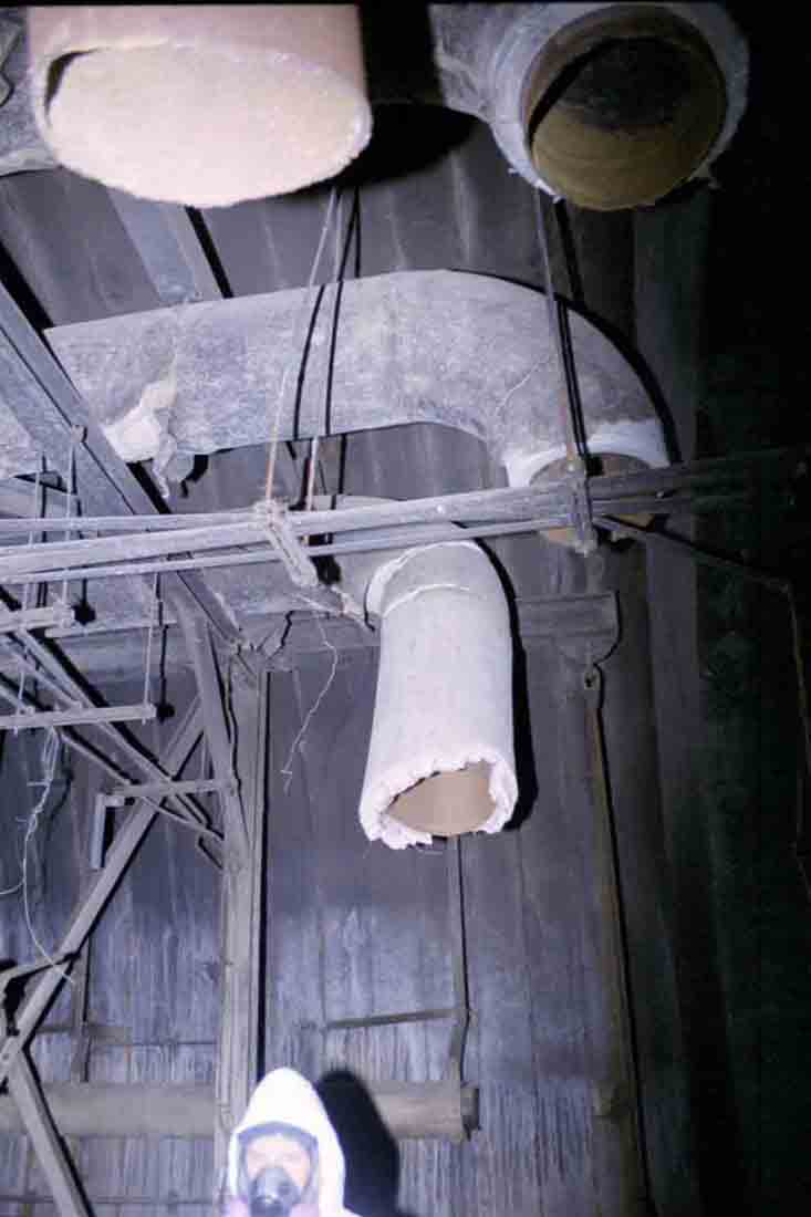
Silo
Gnome looking for all the world like he's about to become the unwitting
comic victim of some devastating downpour of vile effluvia from above.
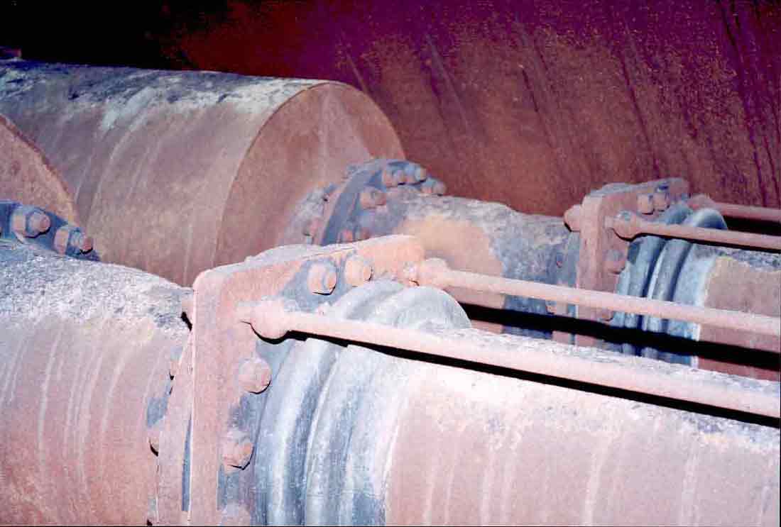
The
pipes are of course the remnants of the diesel exhaust conduits where at
this point two 90-degree offsets conduct the exhaust upwards toward four
gargantuan mufflers in the ceiling on the other side of the nearby
bulkhead. Here you can see where a generous amount of
high-asbestos-content plaster is still in place. Removal of the
piping was obviously too much trouble beyond this point to be bothered
with by the time-constrained salvage contractors.
|
|
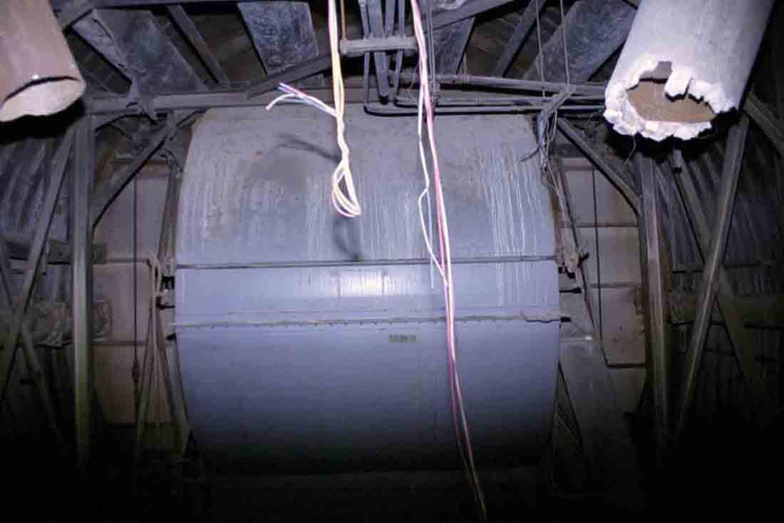
The
Trane Co. squirrel-cage fan with exhaust lines running overhead.
You can see the steel bulkhead separating the raw exhaust discharge from
the interior of the complex behind the fan. Overhead the exhaust
lines pass through the bulkhead to the mufflers on an upper platform
which I'll show you shortly.
|
As
was the case elsewhere in the complex, the electric motor for the fan
had been salvaged. I later saw the sort of motor which was used
with these units and they are quite large and heavy as you would
expect. They are not really all that interesting however, but
typically they used 3-phase power and were usually made by GE.
Not
visible in the above photo is the narrow access door to the right side
of the fan that leads through the bulkhead.
|
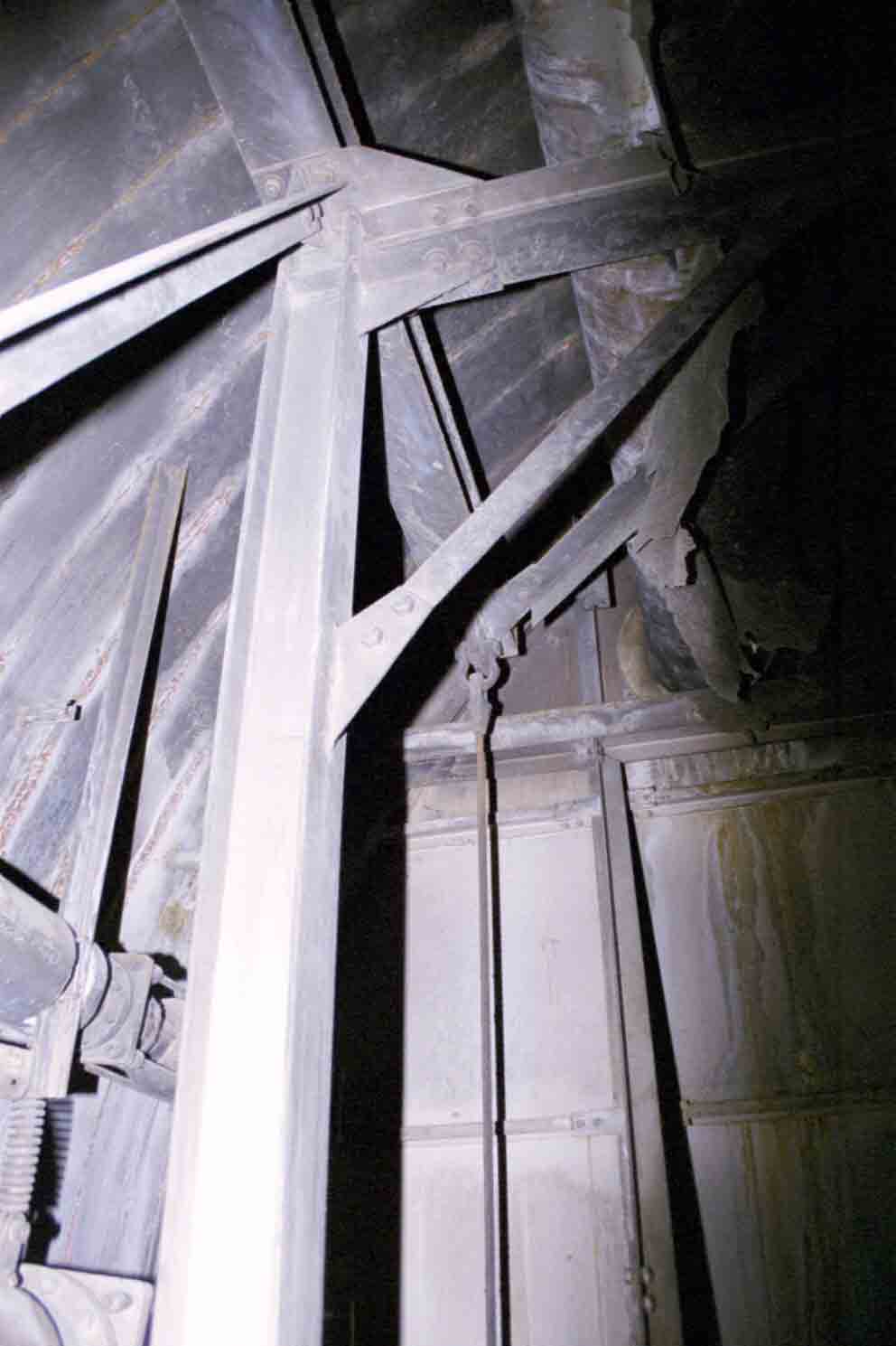
A
view of steelwork and supports at the bulkhead. The fan in the
exhaust tunnel, like that of the intake is mounted on a
"floating" platform to arrest vibration both from and to the
fan and motor. The steel cable is part of the suspension
supporting the platform. Other smaller exhaust lines can be seen
at left, also shock mounted with springs and flexible couplings.
These lines often carried steam, or vapors from lubricants, diesel or
acids employed in the raw water treatment system.
|
|
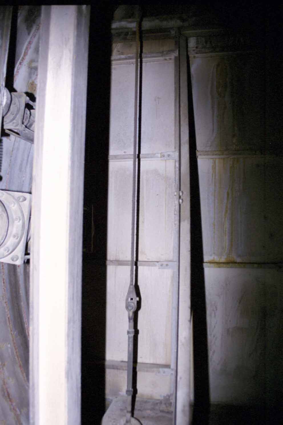
Another
view of the bulkhead and supports. Arguably the most fascinating
photo so far, I know.
|
Heading
through the access door and taking a long step down (about 3') affords
you a view of the sooty tail-end of the exhaust tunnel. The
picture below shows the exhaust fan as seen from beneath the muffler
platform. This area was extremely dirty and badly rusted from its
proximity to the outside air.
|
The
outlet of the exhaust fan: it blows big-time! The ladder leads up
to the mufflers on an overhead platform. The impeller is
surprisingly small compared to the housing that contains it.
|
Heading
up the ladder, we see the colossal mufflers. Head room was a bit
sparse in places and the darkness swallowed up my puny camera flashes
voraciously. I did what I could, but I wish I could have had a
digital camera back then.
|

On
the upper platform: Flex connectors to the mufflers where they penetrate
the steel bulkhead.
|
|
The
absolute most massive mufflers I am likely ever to see! (or anyone else
for that matter) Everything in this area was covered in thick
black soot. I imagine this area was as black as coal during
operation. Only four decades of cold and humidity have made the
soot slowly exfoliate and account for it looking this clean here.
|
|
Looking
back toward the bulkhead and Power House. These mufflers are about
4' in diameter and around 15' in length. I bet you can't find
these at NAPA.
|
|
Looking
toward the blast valves. The accumulated soot is several inches
deep on the far ends. I strongly suspect no one ever ventured in
here while the generators were operating!
|
|
Large
flappers on the ends of the mufflers.
|
Below:
Another narrow access door leading to the blast valves.
|
Looking
toward the blast valves in the direction of airflow. Diesel
exhaust was drawn down from the mufflers above and out to the surface
through a steel grille. A steam vent protrudes into the image from
the left side.
|
For
anyone who might foolishly think of attempting to gain access to a Titan
site through the air intake or exhaust: let me tell you that you will
definitely not fit through the gap between the valve and the opening;
and if you could, its not likely you'd make it past the supports on the
actuator. Add to that the danger of descending (and later
ascending) some 50' by rope into a pit with water at the bottom and I
should hope you have ample deterrent from any such endeavors.
|
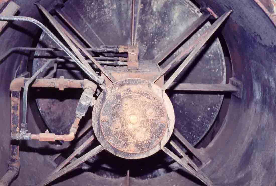
A
close-up of a soot-encrusted 48" blast valve.
|
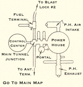
From
here you can head back to the Power House,
check out the Power House Intake,
return to the Main Tunnel Junction
(T.J.#10) or visit other points of interest using the map
below:
Current
Location: Power House Air Exhaust
|
Where
would you like to go next?
|

|
Contact
| Site Map | Links |
Hosted by
InfoBunker

|