Antenna
Terminal Part II
When
I first laid eyes on the antenna terminal at Lowry 725-A in 1994, I
had absolutely NO IDEA what the hell I was seeing.
None. There were helpful signs on the blasts doors to each silo
stating: ANTENNA SILO A and ANTENNA SILO B. That gave me a bit
of a clue, but only a little. Gazing about in the darkness at
the mysterious equipment, dust swirling in the swath of my flashlight,
I tried to discern exactly what the function of all the bewildering
forms I saw might be.
Uneducated
as we were as to U.S. missile systems past and present and their
guidance systems, my fellow sojourners and I could only grope blindly
in the dark (much as we were doing in real life at that moment) at
theories regarding what we saw.
In
most cases I'm sure we were way off.
|
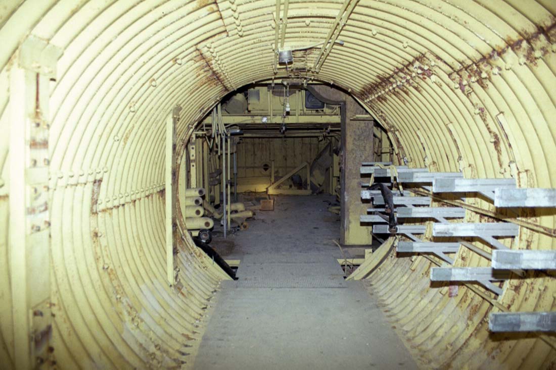
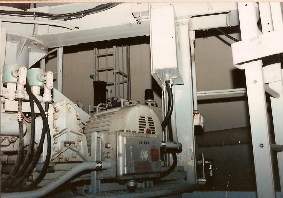
The
antenna terminal room begins straight ahead where the tunnel widens.
Flanking this aisle were rows of control equipment for climate controls,
the antennas, communications and a cabinet of guidance hardware.
|
It
would be nearly seven years before I would see such a sight
again. A series of implausible events would bring me to Lowry
724-C in the Fall of 1999 to inspect the site with a potential buyer
where I found the surreal scenery familiar but somehow different.
I
was more educated this time; I knew I was looking at a Titan I complex
and was generally familiar with the layout and features of the site
but I was still bewildered by most of what I saw. Also, I found
that I could not escape the nagging feeling that although this was
another Titan I site I was seeing, it was somehow different in many
ways from the one I'd seen some six years earlier.
|
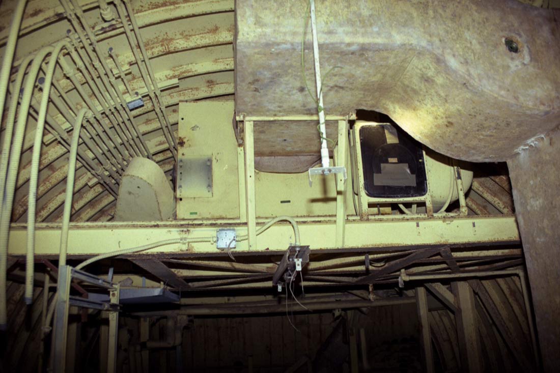
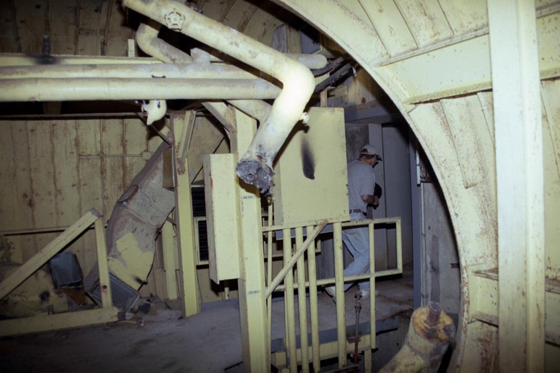
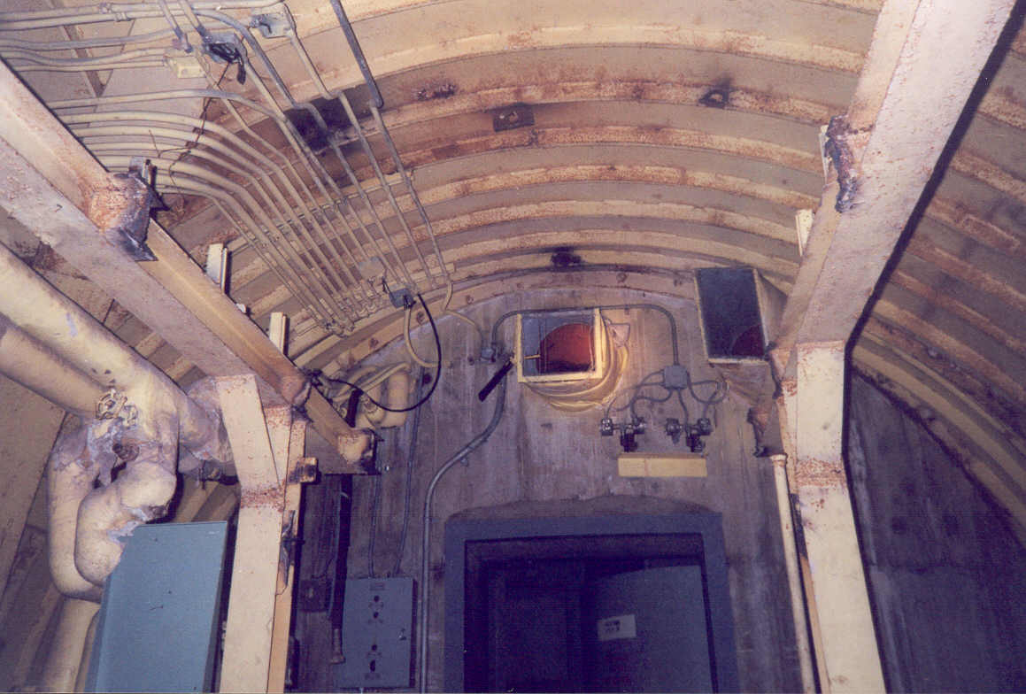
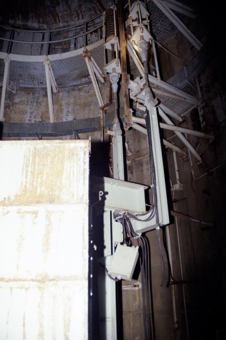
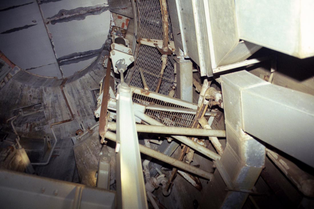
The
antenna
terminal room, looking upward at the overhead platform where the heating
and cooling equipment hides. The electric motors were gone as per
usual but everything else up there appeared to be untouched. Ahead
and to the left and right (not visible here) are the antenna silos.
|
Most
of what seemed different could likely be attributed to poor memory as
I didn't get any photos of 725-A while I was there-- something I
regret deeply. Hell, I didn't even own a cheap camera back then,
let alone one that could pierce the darkness and capture images of
reasonable quality.
As
I looked around 724-C, things seemed odd, out of place and it became
clear that the two sites had been dismantled in very different ways
and to varying degrees in the many parts of the complex.
|
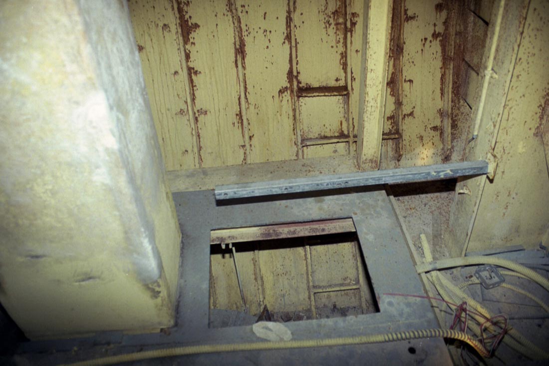
Terminal
room at the personnel tunnel end--basically this is what you see when you first
enter the antenna terminal and turn to look to the left. Cabinets of equipment once straddled
openings in the floor where chilled air was forced up from below to keep
the delicate electronics cool. This hole is actually an access
panel and cable pass-through for a pneumatics control panel that was once
mounted above it. On the left is the insulated supply duct that
cooled the cabinets.
|
|

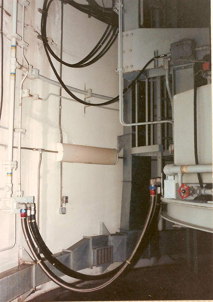
A
tangle of hot and cold water supply and return lines. All these
pipes are currently suspended by hoses on each end and little
else. It's amazing that they haven't collapsed under their own
weight. If you look closely you can see a very taut section of
black rubber hose attached to the pipes and passing behind the curved
beam at a 45 degree angle. This end of the pipes are resting partly
on the gray pedestal just right of center.
I
was particularly wary of standing under this death trap.
|
|
Tunnel
section connecting the 2 silos. You may be wondering: "Hmm.
I bet hitting my head on that jagged pipe while not wearing a hard hat
would probably hurt."
The
answer: HELL YES!
Remember
folks, always wear your safety gear when visiting an old missile complex.
The Titans are a vengeful lot and will seize any opportunity to damage or
dismember you.
|
|
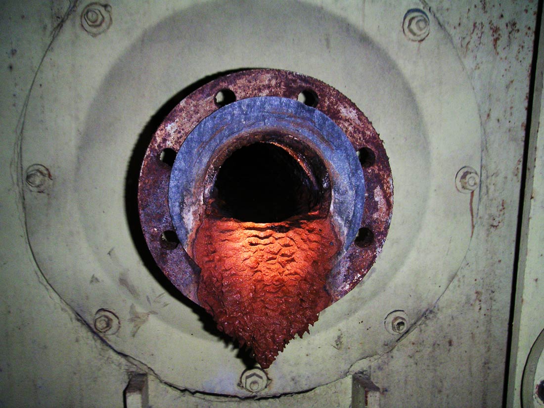
2005:
I noticed this colorful formation on my last visit to 724-C. It is
a stalactite of iron oxide deposits encrusting a flange on the sump
discharge line formed by ongoing water seepage since the 1970's.
|
We
did our best to guess what some of the strange equipment around us was
for, but I suspect that in all but the most obvious cases we were way
off the mark. This area was really dry since the tunnel that
leads to the antenna silos slopes upward to an elevation about 20 feet
higher than that of its entrance. Any water that entered this
area quickly flowed down the tunnel back toward the main
tunnel junction.
|
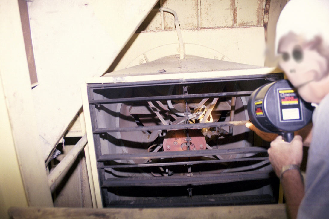
1999,
724-C:
Mr. X assists with the photographing of the exhaust vent and blast valve
therein. This vent extends out and runs to the surface. You'll have to forgive the rather grim visage produced by
obscuring Mr. X's face.
|
|
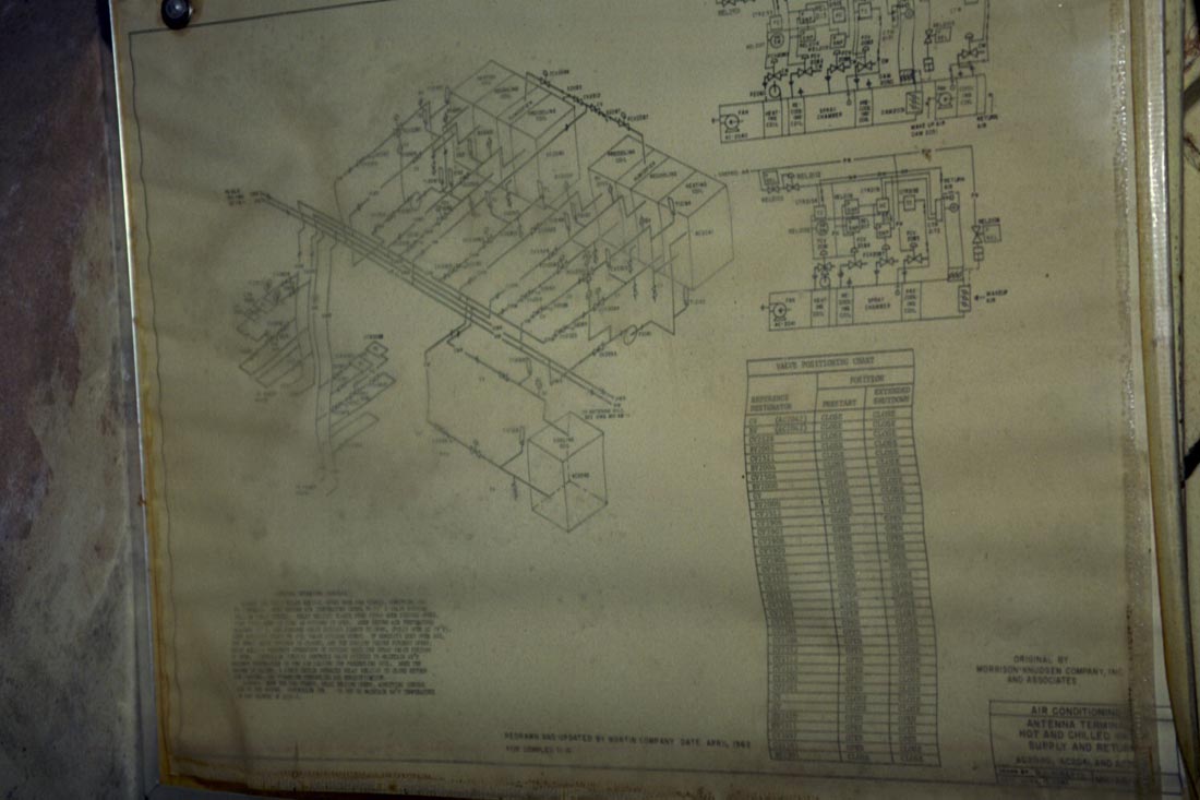
Schematic
titled "Antenna Terminal Hot and Chilled Water Supply and
Return" mounted outside of antenna silo A detailing the intricate
plumbing and proper valve positions in the antenna terminal.
|
|
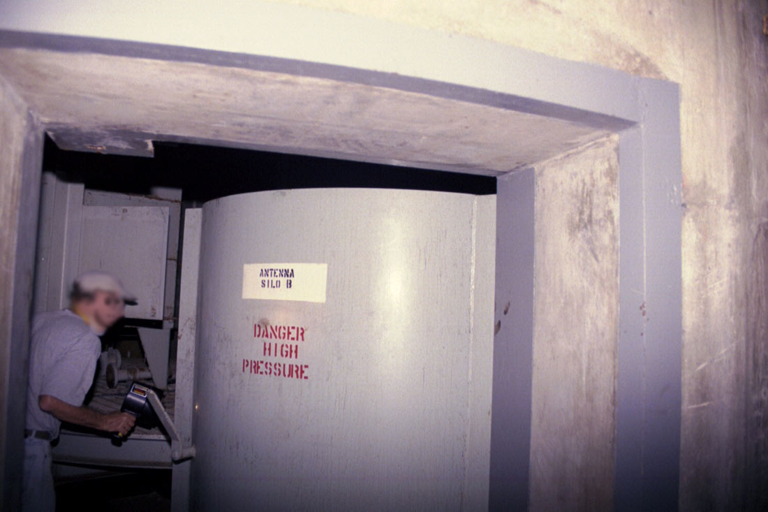
In
between the silos looking from silo A toward silo B, 1999:
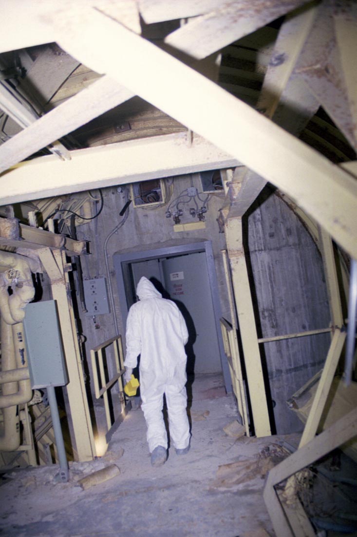
Environmentally encapsulated, I lurch toward the silo door. The
hazardous pipes hang at the middle left.
|
|
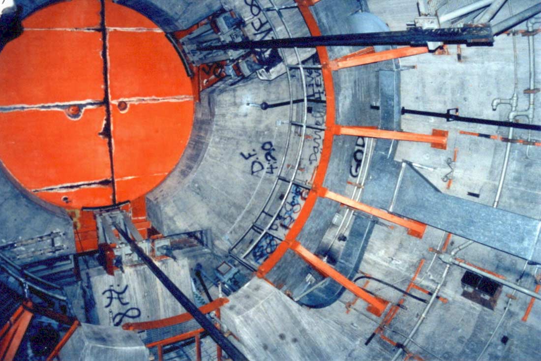
1999:
Door to antenna silo B and blast dampened ductwork above. You can
see here that a section of the I-beam structure was cut out from
overhead. Perhaps to allow clearance for removal of some of the
climate systems equipment.
|
|

1999:
This is basically an indicator panel except for the over ride
switch. From top to bottom, the labels read:
"Antenna
#2 Panel" -
The designation Antenna #2 and B are used interchangeably in blueprints.
"Ant.
& Fire Door Open"
- Refers to the blast door at the personnel level and not the silo
doors.
"Antenna
Door Open" -
Refers to the silo doors at the surface.
"Antenna
Door Closed"
- Refers to the silo doors at the surface.
"Interlock
Over Ride" -
This switch allows both silos to be open (soft) at the same time during
maintenance, installation or repairs. Normally this is prevented
by the interlock mechanism to prevent both antennas from being
vulnerable to attack simultaneously.
|
|
1999:
Blast door at antenna silo B. This is exactly the same type of
door used in the blast
locks to protect
the launcher areas. This photo shows the wall thickness of the
silo at the doors where they are heavily reinforced.
|
|

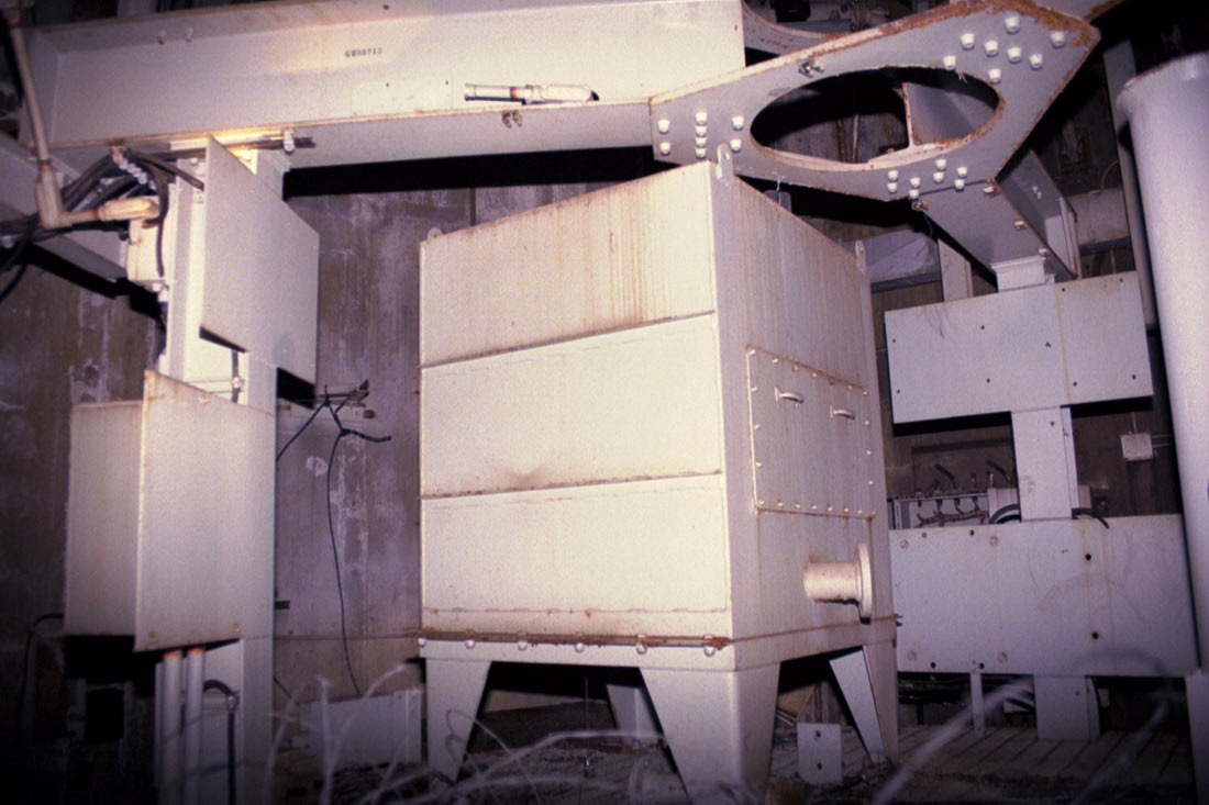
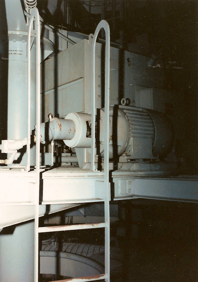
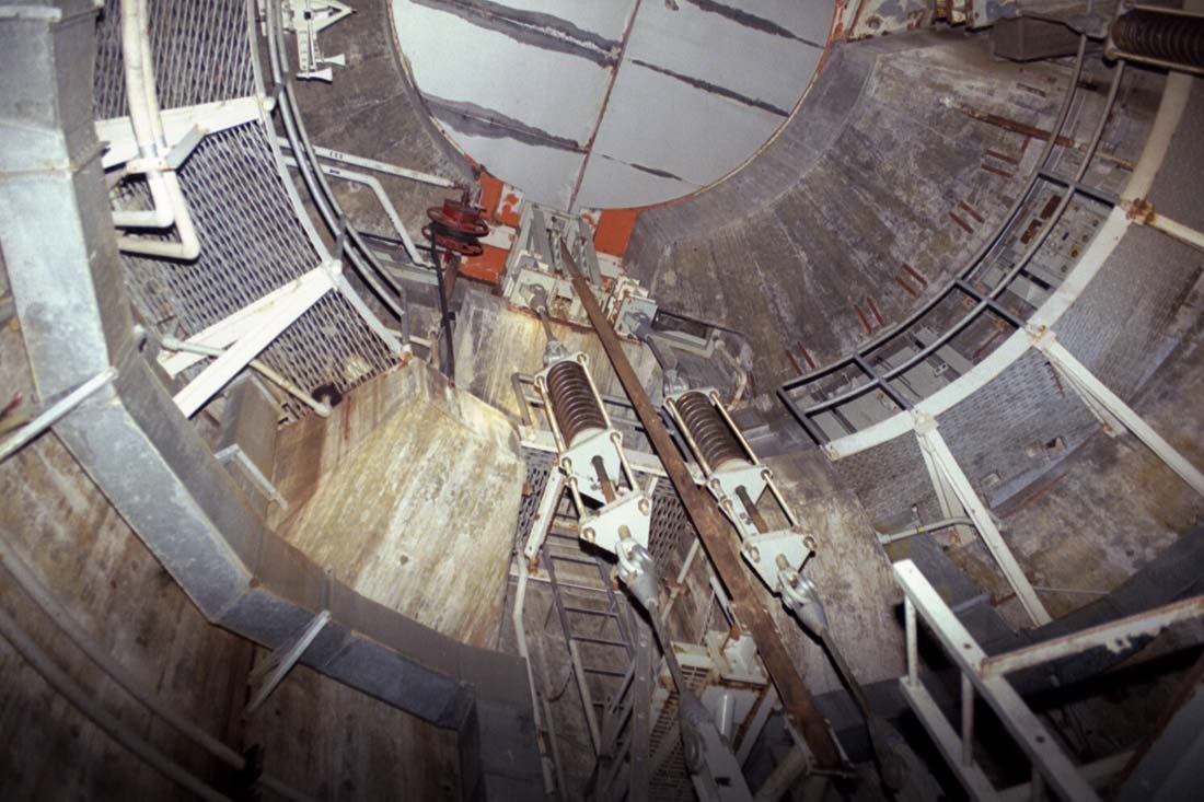
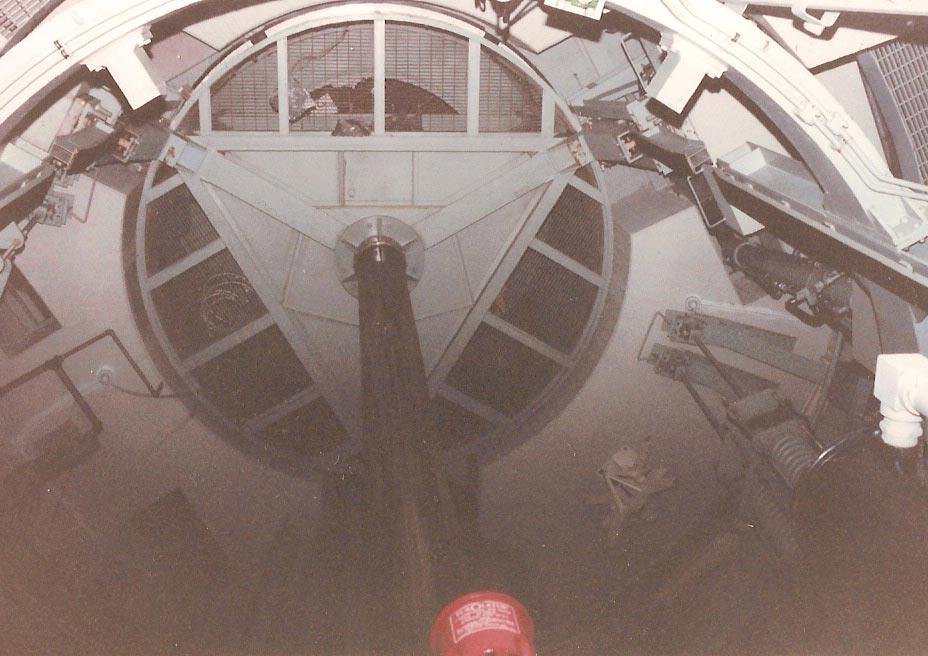
1999:
The
lower platform of the antenna where the hydraulic pump and accumulator
and other equipment were located. Note the hole in the center of
the structure to allow for the hydraulic ram to pass. Though
flooded, the area below is about 23 feet deep.
|
|
1999:
Hydraulic reservoir for the antenna platform and doors. The
platform on which this gear rests is suspended from above by six
insanely robust steel cables.
|
Of
course all the operational sites are pretty much trashed or scrapped
out rather heavily so it is difficult to tell what the complex looked
like before it was salvaged, graffiti-tagged, flooded and left to rot
for decades. If only there were some example of what things once
looked like before the ravages of time and trespassers took their
toll. (if only!)
It
just so happens that there is. (sort of)
California
is not only the home of Beale AFB which had its own Titan I squadron,
the 851st SMS, but also the home of Vandenberg AFB and the Titan I
OSTF.
In
order to test the integration of major systems of the WS-107A-2 prior
to the activation of the first operational squadron, a Titan I
facility was constructed at Vandenberg AFB and was designated the
Operational System Test Facility or OSTF.
The
OSTF was a scaled-down version of a Titan I operational complex.
It had only 1 launcher silo, one antenna terminal and the power house
and control centers were above-ground block-house style buildings
instead of heavily hardened domed structures.
|
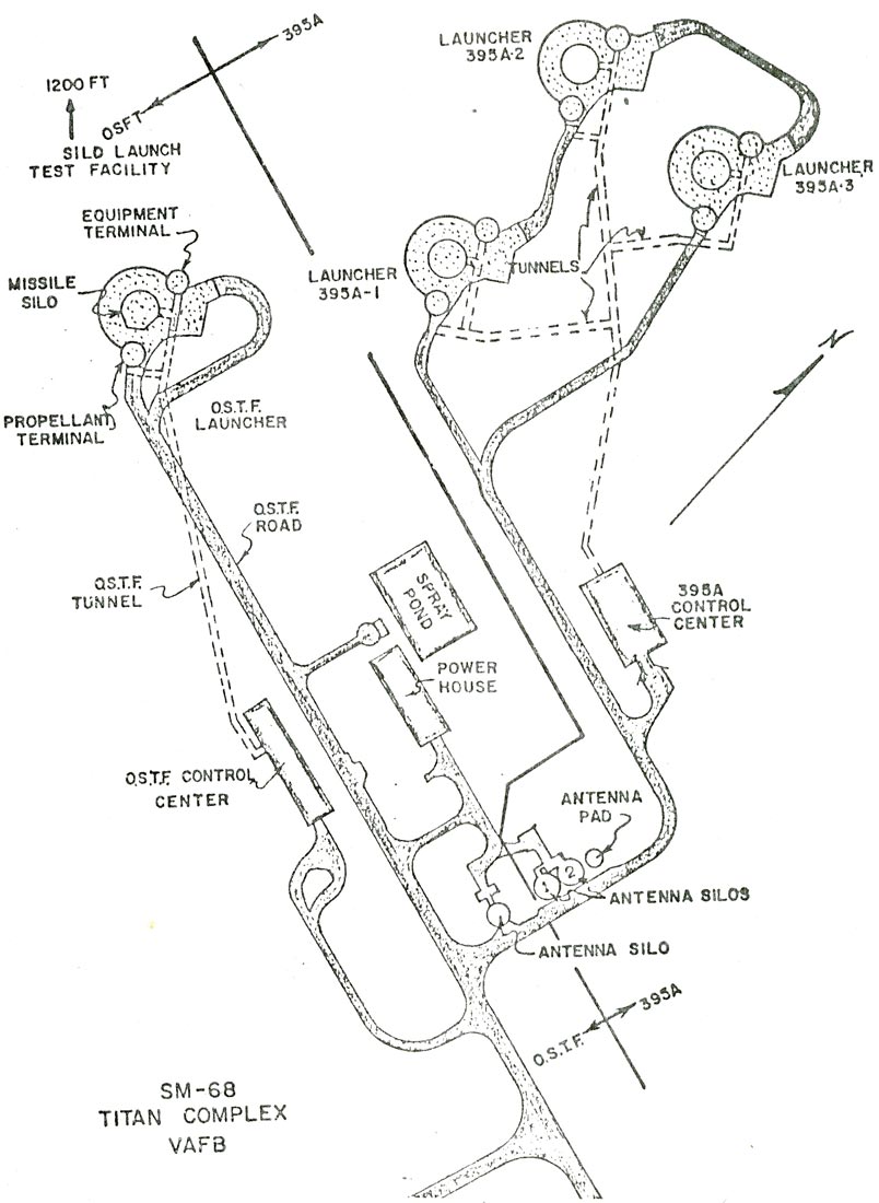
Diagram
of the Titan I OSTF (on the left) and the 395-A Test Facility at
Vandenberg AFB showing the single launcher and antenna silo.
Image
courtesy of Fred Epler
|
The
OSTF was short-lived however and the launcher silo and nearby
structures were destroyed or severely damaged in December 1960 by an
explosion during a dual-propellant loading exercise. The
dual-propellant loading exercise (PLX) meant
that both LOX and RP-1 were onboard the missile during a simulated
launch-- a rare test due to the obvious hazards presented by the
situation. Normally only RP-1 or LOX were loaded
alone on the missile during exercise-- not both at the same time.
A
fully-loaded missile was being lowered back into the silo when it was
observed that its descent was abnormally rapid-- the result of a
failed braking system on the launcher elevator. Unhindered as it
was, the missile, its fuel, and oxidizer all plunged to the bottom of
the silo where the airframe and its tanks were split wide open under
the impact. The volatile LOX ignited producing a tremendous
explosion that rendered the facility unusable and too costly to
repair. Unbelievably, no one was injured by the blast that threw
debris miles away from the complex.
Since
the accident, the OSTF has remained relatively untouched mostly,
leaving its single antenna silo (which was located a good distance
from the silo) in very good shape.
Mr. Lance
Wright was fortunate enough to be able to see the site in person some
years back and took lots of pictures of this very rare Titan I antenna
silo that hasn't been completely scrapped out.
Thanks
to Lance and Fred, I can share those photos with you here:
|
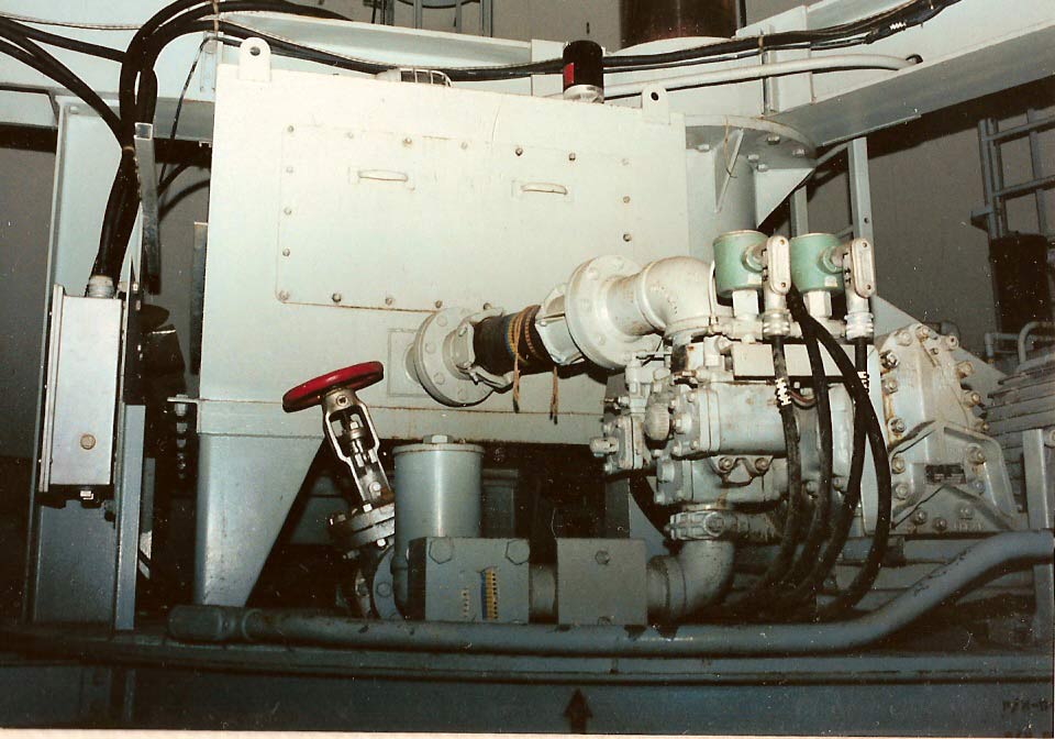
OSTF
antenna silo: Here
is the very same platform as in the previous photo with the hydraulic
reservoir and all the equipment just as it was installed in the
operational sites. A little grimier perhaps, but otherwise
unchanged. The plumbing, electrical and hoses are all in place and
unmolested.
Image
courtesy of Fred Epler, photo by Lance Wright
|
|
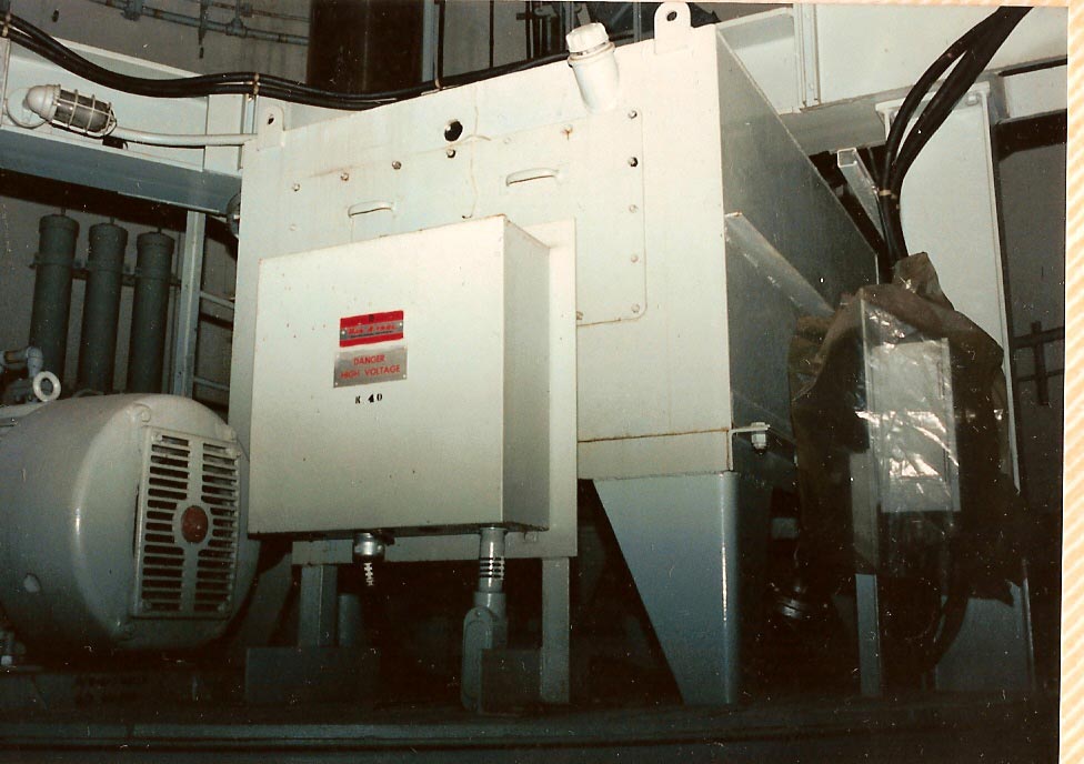
Another
look at the platform in the OSTF antenna silo showing the hydraulic
equipment. Even the electric motors have been left
undisturbed! Note the plastic that has been placed over the
electrical control box on the right.
Image
courtesy of Fred Epler, photo by Lance Wright
|
|
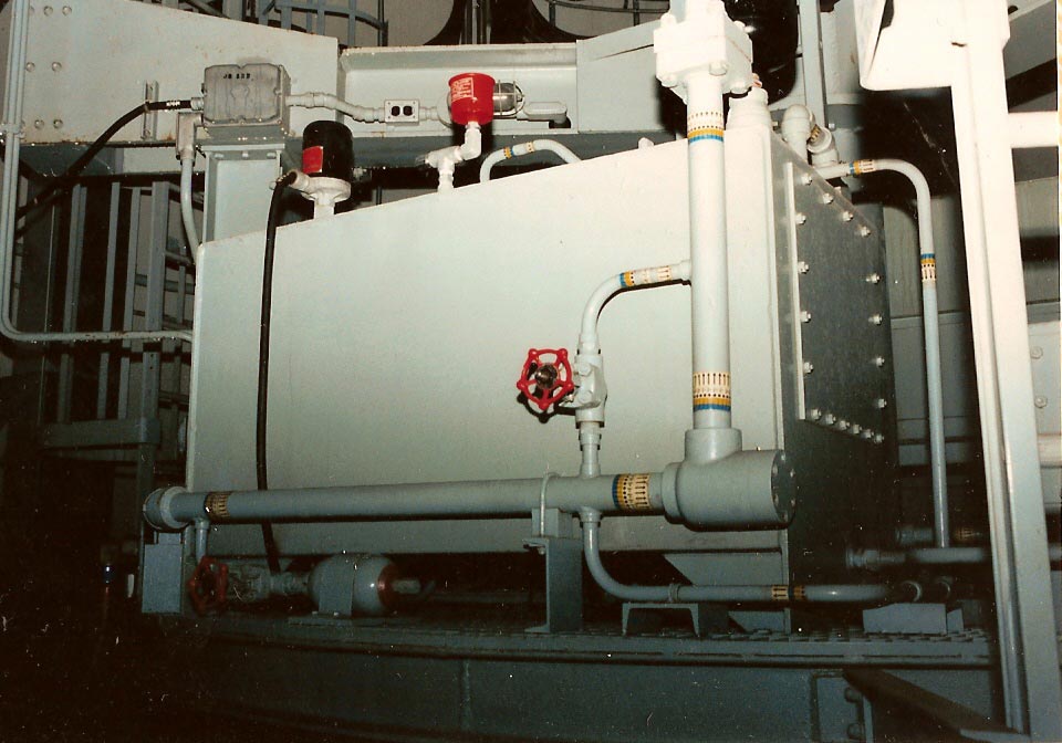
OSTF
antenna silo. Another view of the hydraulic equipment.
Image
courtesy of Fred Epler, photo by Lance Wright
|
|
OSTF
antenna silo. You can see a ladder to the catwalk level in the
background. These ladders were removed at 724-C making ascension
rather more difficult!
Image
courtesy of Fred Epler, photo by Lance Wright
|
|
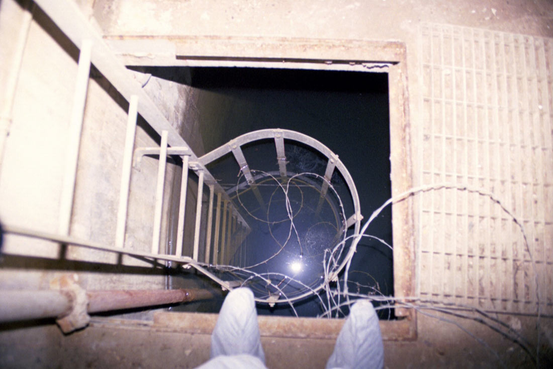
1999,
724-C: the lower level of both antenna silos were almost completely
flooded. That's about 23 feet of water down there. Not sure
why the barbed wire is there. Most likely it was thrown in while
the doors were open during salvage operations.
|
|
Lower
level of antenna silo at the OSTF: the column you see here is the
hydraulic ram that raised the antenna to the surface. This was
removed from all operational sites I've ever seen.
Image
courtesy of Fred Epler, photo by Lance Wright
|
|
1999,
724-C: space between the platform and the silo walls
|
|
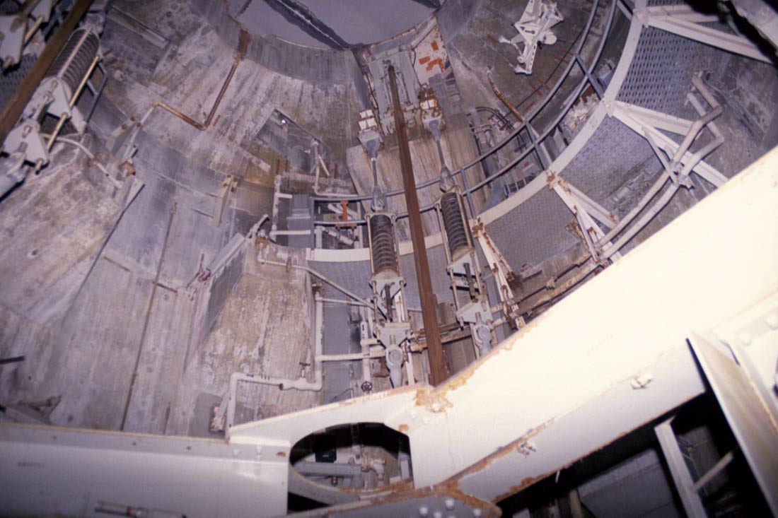
1999,
724-C: looking up toward the catwalk level. Here you can see one
of the 3 pairs of shock-mount springs that supported the antenna
platform and allowed it to sway while the silo was in "Hard"
condition (silo doors closed).
|
|
OSTF
antenna silo: Flexible hydraulic lines bridging the gap from the
equipment platform to the silo wall to supply power to the silo doors.
Image
courtesy of Fred Epler, photo by Lance Wright
|
|
OSTF
antenna silo: equipment platform and high-pressure hydraulic pump unit
Image
courtesy of Fred Epler, photo by Lance Wright
|
|
1999,
724-C: Looking up toward the catwalk level. You can just see a bit
of the silo doors overhead.
|
|

2005,
724-C: Another look up at the catwalk level
|
|
1999,
724-C: Looking up at the doors and catwalk. One leg of the antenna
platform support and shock mount runs down the center of the photo.
|
|

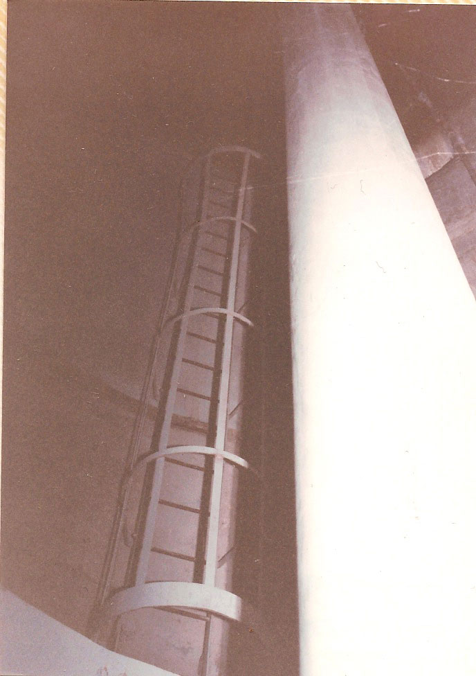
1999,
724-C: Looking up once more. You can see a ladder on the left side
leading to a small service platform. That is just a section of
aluminum extension ladder tied in place with a scrap of wire.
Another service ladder leads further up to the catwalk. This is
the same ladder I dragged all the way to propellant terminal #1 so I
could explore the LOX tunnel.
The
real access ladders for both silos appear to have been cannibalized and
used for climbing makeshift towers on the surface which were fashioned
from the old missile flame buckets.
|
Of
course I was very keen to see what exactly might be up on the catwalk
level of the antenna silos and this was where one of my first rather
hair-raising episodes of exploring the site came in. Up to this
point I had braved asbestos, unknown chemical contaminants and murky
water of unknown depths, floors with gaping holes in them which
invited a 16-foot drop to a concrete floor littered with jagged metal
debris, narrow and dark enclosed spaces, treacherous and slippery
metal stairs covered with condensation and spooky, unexplained noises
as I explored the complex.
As
unsettling as all those trials were, this was worse. This was an old
section of aluminum ladder about 16 feet long that under the
circumstances could only be charitably described as unstable.
Now
16 feet doesn't look or sound like much, that is until you turn it from
horizontal to vertical and then put yourself at that height, in the
dark, and are supported only by questionable means. Such was the only route up
to the catwalk level owing to the removal of the original ladders.
|
1999,
724-C: Guide rail and shock mounts again at center with the silo doors
far overhead
|
|
For
comparison, this is a shot inside of a Washington state Titan I antenna
silo. Similarly scrapped but livened up with primer-red
appointments. One major difference is the complete removal of the
the suspended antenna platform. Only the guide rails remain of the
antenna elevating mechanism at this site.
Photo
courtesy of Walter Silva
|
|
Back
at the OSTF: The raised elevator platform and supporting ram. The
actual antenna appears to be gone, but its hard to tell in this
shot. Given the height to which the platform is raised with the
doors closed, it would seem that the entire antenna pedestal and
assembly must have been removed.
Image
courtesy of Fred Epler, photo by Lance Wright
|
There
was no way I was letting a shaky ladder deter me, nervous though I
was. In hindsight this ladder would turn out to be a mere trifle
compared to the absolute white-knuckle terror of the Insane
Missile Silo Ascents I would
make a few years later, but at the time, as the aluminum rig pitched
to and fro and rattled and shook as I climbed, my fear certainly kept me
focused on what I was doing!
When
I reached the small platform about 10 feet below the catwalk, I found
the ladder lashed rather carelessly in place with a piece of twisted
wire and a decaying length of rope. Well, at least there was a
backup!
The
over-built steel access ladder up to the catwalk was far more
reassuring and after a brief rest and a few photos, I continued upward
to the higher reaches of the antenna silo.
Well,
enough of this neck-strain from looking straight up! Next we'll
get a look around from the catwalk and explore further.
Antenna
Terminal Cont.

|
Contact
| Site Map | Links |
Hosted by
InfoBunker

|