|
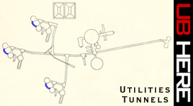
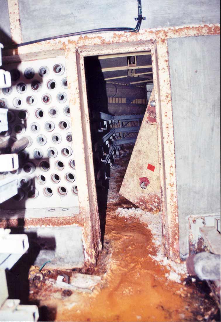
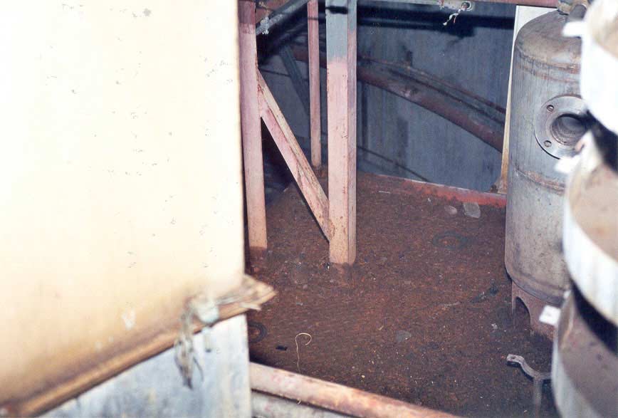
Top
down view of the utilities tunnel showing its basic structure and 2
corners: one of 33 degrees just beyond level II of the equipment
terminal on the right, and one of 22 degrees as it enters the missile
silo.
|
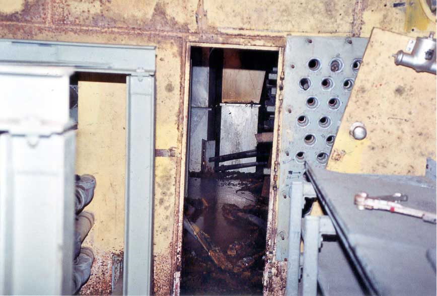
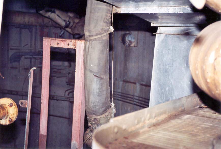
The
utilities tunnels are simple interconnecting tunnel structures
consisting of a standard 9'6" diameter type "A"
personnel tunnel made of corrugated steel sections with 6 inches of
concrete in the bottom to make a level floor.
Each
of the missile silos and equipment terminals were connected by these
tunnels from level II on the equipment terminal to about 60 feet down on
the inside of the missile silo where it emerged next to the fuel crib.
As
the name suggests these tunnels carried various utilities and services
from the equipment terminal into the missile silo and in some cases,
directly to the missile itself.
|
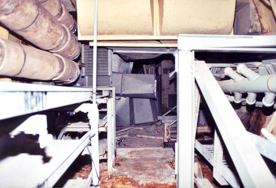
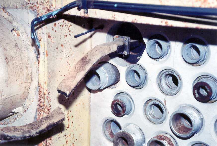
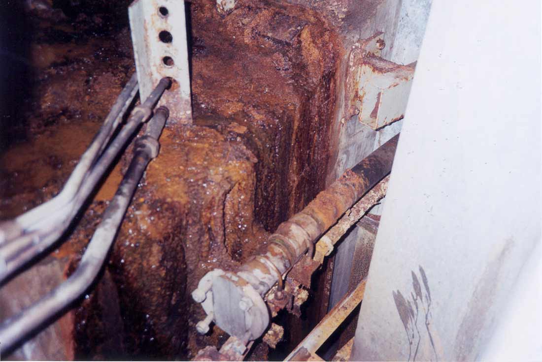
Tunnel
section of the utilities tunnel at the firewall located 10 feet before
the missile silo which shows openings and penetrations for power, AC,
guidance, hydraulic lines and other plumbing and services.
|
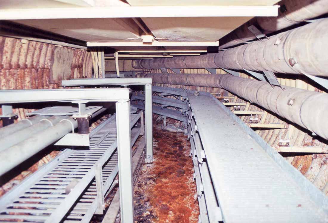
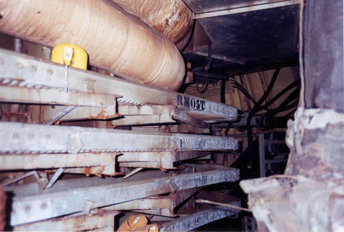
Services
running through these tunnels included air conditioning, power, water,
guidance signals, hydraulic lines, utility air for powering pneumatically
controlled dampers and actuators and other cabling and
plumbing.
These
pictures are of 724-C from launchers #1 and #2. Launcher #3 was
flooded such that the entire utilities tunnel and in fact the bottom 2
levels of the equipment terminal were flooded. Launcher #2 was
also very wet and the lowest level (level I) of the equipment terminal
was completely flooded.
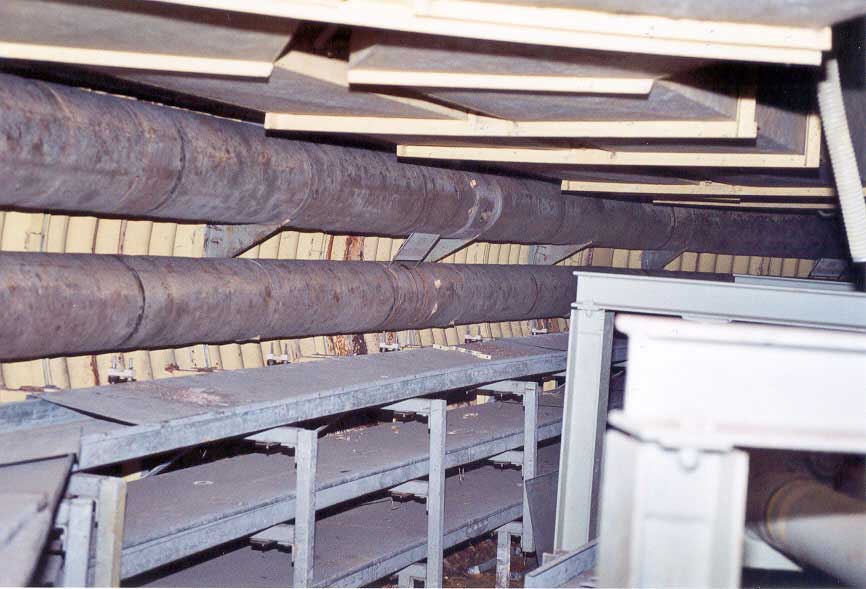
As
you can see, even after salvage that the tunnels were pretty crowded
with cable trays, conduit and ductwork. The above photo shows
insulated heating and cooling air ductwork for the missile at the
upper left and cable trays below. Top middle you see what are
most likely supply ducting to the missile silo itself
and hydraulic lines and more cable tray on the right.